UART is the simplest serial protocol, but the devices that speak it are some of the most interesting: GPS receivers that decode satellite signals into latitude and longitude, Bluetooth modules that turn a wire into a wireless link, and RS-485 transceivers that push serial data hundreds of meters over twisted pair. This lesson connects all three to the Blue Pill, each on its own USART peripheral, and builds a GPS tracker that relays coordinates to your phone and to a remote display node. #STM32 #UART #GPS
What We Are Building
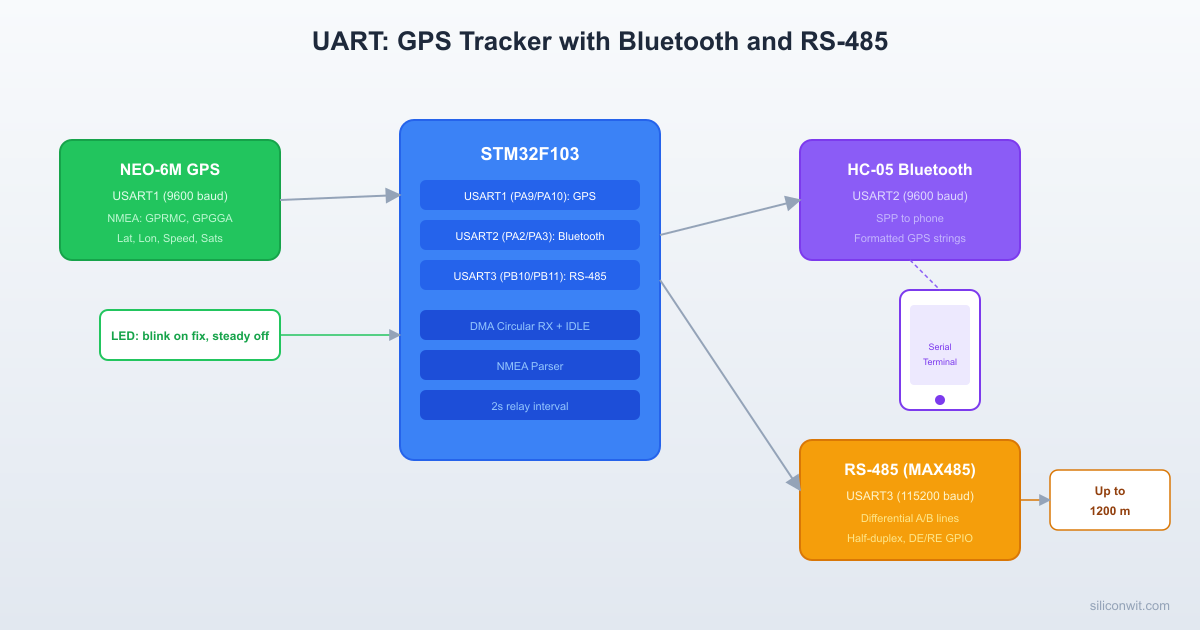
GPS Tracker with Bluetooth Phone Relay
A position tracker that reads GPS coordinates from a NEO-6M module, formats them into readable strings, and sends them to a phone over Bluetooth for live map display. Simultaneously, the same position data is forwarded over RS-485 to a remote node that could be hundreds of meters away. An LED blinks on each GPS fix and stays steady when there is no satellite lock.
Project specifications:
Parameter
Value
Board
Blue Pill (STM32F103C8T6)
GPS
NEO-6M on USART1 (9600 baud)
Bluetooth
HC-05 on USART2 (9600 baud)
RS-485
MAX485 on USART3 (9600 baud)
GPS update rate
1 Hz (default NEO-6M rate)
Data relay interval
Every 2 seconds
DMA
Circular buffer on USART1 RX with idle line detection
Bill of Materials
Component
Quantity
Notes
Blue Pill (STM32F103C8T6)
1
From previous lessons
ST-Link V2 clone
1
From previous lessons
NEO-6M GPS module
1
Comes with ceramic patch antenna
HC-05 Bluetooth module
1
SPP (Serial Port Profile) module
MAX485 module
2
One for each end of the RS-485 link
120 ohm resistor
2
RS-485 line termination
LED + 330 ohm resistor
1
GPS fix indicator
Breadboard + jumper wires
1 set
From previous lessons
UART Protocol Review
UART (Universal Asynchronous Receiver/Transmitter) sends data as a series of frames. Each frame contains a start bit (always low), 8 data bits (LSB first), an optional parity bit, and one or two stop bits (always high). The baud rate defines the bit duration: at 9600 baud, each bit lasts approximately 104 microseconds.
Hardware flow control uses two additional lines: RTS (Request To Send) and CTS (Clear To Send). The receiver de-asserts CTS when its buffer is full, and the transmitter pauses. This prevents data loss at high speeds or when the receiver is busy.
Software flow control sends special characters (XON = 0x11, XOFF = 0x13) inline with data to signal the sender to pause or resume. This works without extra wires but cannot be used with binary data that might contain those byte values.
For this project, all three UART links run at 9600 baud with no parity, 8 data bits, 1 stop bit, and no flow control. The NEO-6M and HC-05 both default to these settings.
Wiring
GPS Tracker Data Flow
┌──────────┐ USART1 ┌──────────────┐
│ NEO-6M ├─────────>│ Blue Pill │
│ GPS │ NMEA │ (STM32F103) │
│ Module │ 9600 │ │
└──────────┘ baud │ Parse NMEA │
│ Extract │
┌──────────┐ USART2 │ lat/lon │
│ HC-05 │<─────────┤ │
│Bluetooth │ coords │ │
│ to phone│ 9600 │ │
└──────────┘ baud │ │
│ │
┌──────────┐ USART3 │ │
│ MAX485 │<─────────┤ │
│ RS-485 │ coords │ │
│ (remote)│ 9600 │ │
└──────────┘ baud └──────────────┘
STM32 Pin
Function
Connected To
PA9
USART1_TX
NEO-6M RX
PA10
USART1_RX
NEO-6M TX
PA2
USART2_TX
HC-05 RX
PA3
USART2_RX
HC-05 TX
PB10
USART3_TX
MAX485 DI
PB11
USART3_RX
MAX485 RO
PB1
GPIO Output
MAX485 DE + RE (tied together)
PC13
GPIO Output
GPS fix LED (onboard, active low)
3.3V
Power
NEO-6M VCC, HC-05 VCC
5V
Power
MAX485 VCC (if 5V module)
GND
Ground
All modules GND
RS-485 MAX485 Wiring Detail
MAX485 Pin
Connection
DI
PB10 (USART3_TX)
RO
PB11 (USART3_RX)
DE
PB1 (direction GPIO)
RE
PB1 (tied to DE, active low for receive)
A
Twisted pair wire A (to remote MAX485 A)
B
Twisted pair wire B (to remote MAX485 B)
VCC
5V (or 3.3V for 3.3V modules)
GND
Common ground
The DE (Driver Enable) and RE (Receiver Enable, active low) pins are tied together. When the GPIO is high, the module transmits. When low, it receives. This is half-duplex: you cannot transmit and receive simultaneously on the same MAX485.
CubeMX Configuration
Create a new project for STM32F103C8Tx. Set debug to Serial Wire.
Configure USART1 (GPS). Mode: Asynchronous. Baud Rate: 9600, Word Length: 8, Stop Bits: 1, Parity: None. Enable DMA for USART1_RX: Mode = Circular, Data Width = Byte. Under NVIC, enable USART1 global interrupt (needed for idle line detection).
Configure USART2 (Bluetooth). Mode: Asynchronous. Same parameters as USART1 (9600, 8N1). No DMA needed; we transmit only.
Configure USART3 (RS-485). Mode: Asynchronous. Same parameters (9600, 8N1). No DMA needed for this simple half-duplex use.
Configure GPIO. Set PB1 as GPIO_Output (RS-485 direction), initial state Low (receive mode). Set PC13 as GPIO_Output (LED).
DMA settings. In the DMA tab for USART1_RX, select DMA1 Channel 5, Direction: Peripheral to Memory, Mode: Circular, Increment: Memory only, Data Width: Byte.
Generate code and open main.c.
DMA-Based UART Reception
Polling UART byte by byte is unreliable for GPS data. The NEO-6M sends bursts of NMEA sentences (often 400+ bytes) once per second, and if the CPU is busy when bytes arrive, they are lost. DMA with idle line detection solves this completely: DMA writes incoming bytes to a circular buffer without CPU intervention, and the idle line interrupt fires when the GPS pauses between sentences, telling you that a complete batch of data is ready.
Circular DMA Buffer Setup
main.c
/* Private defines */
#defineGPS_BUF_SIZE512
#defineBT_TX_SIZE128
#defineRS485_TX_SIZE128
/* Private variables */
uint8_tgps_dma_buf[GPS_BUF_SIZE];
volatileuint16_t gps_dma_head =0; /* Last processed position */
volatileuint8_t gps_data_ready =0;
charnmea_line[128]; /* Single NMEA sentence buffer */
The idle line interrupt fires when the UART RX line has been idle for one frame duration (about 1 ms at 9600 baud). This indicates the GPS module has finished sending its current batch of sentences.
stm32f1xx_it.c
/*
* Idle line detection: choose ONE of the two approaches below.
*
* APPROACH 1 (recommended): Override USART1_IRQHandler in stm32f1xx_it.c.
* CubeMX generates a default USART1_IRQHandler that only calls
* HAL_UART_IRQHandler(). Replace it with the version below so it also
* checks the idle flag. This is the most reliable method because the HAL
* does not provide a built-in idle callback.
*/
externvolatileuint8_t gps_data_ready;
voidUSART1_IRQHandler(void) {
if (__HAL_UART_GET_FLAG(&huart1, UART_FLAG_IDLE)) {
__HAL_UART_CLEAR_IDLEFLAG(&huart1);
gps_data_ready =1;
}
HAL_UART_IRQHandler(&huart1);
}
Processing the DMA Buffer
The circular DMA buffer wraps around automatically. We track how far we have read (head) versus how far DMA has written (tail):
The NEO-6M outputs NMEA 0183 sentences as ASCII text. Each sentence starts with a dollar sign character, a talker/sentence ID, comma-separated fields, an asterisk, and a two-character hex checksum. The two most useful sentences are:
/* Call atoi immediately: nmea_field returns a static buffer,
so the next call would overwrite the previous result. */
gps.fix_quality=atoi(nmea_field(sentence, 6));
gps.satellites=atoi(nmea_field(sentence, 7));
}
HC-05 Bluetooth Module
The HC-05 is a Bluetooth SPP (Serial Port Profile) module. In normal operation, it acts as a transparent UART bridge: bytes sent to its RX pin appear on the paired phone, and bytes the phone sends come out of the TX pin. No special protocol is needed on the STM32 side.
AT Command Configuration
Before first use, configure the HC-05 by entering AT command mode. Hold the button on the module (or pull the EN/KEY pin high) while powering it on. The LED will blink slowly (2 seconds on, 2 seconds off) instead of the fast blink. Connect to USART2 and send commands at 38400 baud (AT mode uses 38400 regardless of the configured data baud rate):
Command
Response
Effect
AT
OK
Test connection
AT+NAME=GPS_Tracker
OK
Set Bluetooth device name
AT+UART=9600,0,0
OK
Set data mode baud: 9600, 1 stop, no parity
AT+PSWD=1234
OK
Set pairing PIN
AT+ROLE=0
OK
Slave mode (phone connects to it)
After configuration, power cycle the module without holding the button. It enters data mode and waits for a Bluetooth connection.
On the phone side, use any Bluetooth serial terminal app (such as “Serial Bluetooth Terminal” on Android). Pair with “GPS_Tracker” using PIN 1234, then connect. GPS strings will appear in the terminal every 2 seconds.
RS-485 Long-Distance Communication
RS-485 uses differential signaling on two wires (A and B). The voltage difference between A and B determines the bit value: A greater than B is a logic 1, B greater than A is a logic 0. Because both wires pick up the same electrical noise, the differential receiver cancels it out. This allows reliable communication over distances up to 1200 meters.
RS-485 Differential Bus (Half-Duplex)
Node A Node B
┌──────────┐ ┌──────────┐
│ STM32 │ ┌────────┐ │ STM32 │
│ USART3 ├──┤MAX485 │ │ USART │
│ TX/RX │ │ DI/RO │ │ TX/RX │
│ PB1: DE │──┤ DE/RE │ │ DE pin │
└──────────┘ │ A ────┼──────┼── A │
│ B ────┼──────┼── B │
└────────┘ [120R] └──────┘
Twisted pair, up to 1200m
120R termination each end
Direction Control
The MAX485 is half-duplex: it can either transmit or receive, not both. The DE (Driver Enable) pin controls direction. Our firmware must set DE high before transmitting, send the data, wait for the last byte to leave the shift register, then set DE low to return to receive mode.
/* Wait for transmit complete (shift register empty) */
while (__HAL_UART_GET_FLAG(&huart3, UART_FLAG_TC)== RESET);
RS485_RX_EN();
}
Simple Request/Response Protocol
For the GPS tracker, the STM32 node sends position data periodically over RS-485. A remote node (a second Blue Pill with another MAX485) can receive and display it. The protocol is simple: each message starts with a header byte (0x02, STX), followed by the payload, and ends with a terminator (0x03, ETX).
main.c
voidrs485_send_position(void) {
if (!gps.fix_valid) return;
int lat_deg = (int)gps.latitude;
int lat_frac = (int)((gps.latitude- lat_deg) *10000);
if (lat_frac <0) lat_frac =-lat_frac;
int lon_deg = (int)gps.longitude;
int lon_frac = (int)((gps.longitude- lon_deg) *10000);
/* Process GPS data when DMA buffer has new data */
if (gps_data_ready) {
gps_data_ready =0;
gps_process_buffer();
}
/* Relay position every 2 seconds */
if (now - last_relay_tick >= RELAY_INTERVAL_MS) {
last_relay_tick = now;
/* Send to phone via Bluetooth */
bt_send_position();
/* Send to remote node via RS-485 */
rs485_send_position();
}
/* Update fix LED */
led_update();
}
}
Sending UBX Configuration Commands
The NEO-6M accepts UBX binary commands alongside NMEA. You can disable unwanted NMEA sentences to reduce the data load. For example, to disable the GSV (satellites in view) sentence on UART1:
/* Add similar commands for other unwanted sentences (GSA, VTG, GLL) */
}
Call gps_configure() once after startup, before the main loop. The NEO-6M acknowledges UBX commands with a UBX-ACK message, but for simplicity we do not parse the acknowledgment here.
Project File Structure
DirectoryGPS_Tracker_UART/
DirectoryCore/
DirectoryInc/
main.h
DirectorySrc/
main.c
stm32f1xx_it.c
DirectoryDrivers/
DirectorySTM32F1xx_HAL_Driver/
…
DirectoryCMSIS/
…
GPS_Tracker_UART.ioc
Testing and Verification
Test GPS reception first. Flash the firmware and open a serial terminal on USART2 (the Bluetooth UART). Before pairing Bluetooth, you can connect a USB-serial adapter to PA2/PA3 to see the output. If the GPS module has a fix (outdoors, or near a window), you should see latitude and longitude. If you see “NO FIX”, wait a few minutes for satellite acquisition. A cold start can take 5 to 15 minutes.
Test Bluetooth pairing. Power on the HC-05 (fast-blinking LED). On your phone, scan for Bluetooth devices and pair with “GPS_Tracker” (or “HC-05” if not yet renamed). Open a serial terminal app, connect, and verify that GPS strings appear every 2 seconds.
Test RS-485. Connect two MAX485 modules with twisted pair or two long jumper wires. On the receiving end, connect another USB-serial adapter to the MAX485 RO pin (or use a second Blue Pill as the remote node). Verify that the STX-framed position messages arrive correctly. Test with a few meters of wire first, then extend to longer distances.
Verify LED behavior. With no GPS fix, the LED should be steady on. With a fix, it should blink (short flash every second).
Production Notes
Bluetooth range. The HC-05 is a Class 2 device with a rated range of about 10 meters. In practice, with clear line of sight, you can get 20 to 30 meters. Walls and metal objects reduce this significantly. For longer range, consider the HC-12 (433 MHz, up to 1 km) or an ESP32 with BLE.
RS-485 termination and biasing. For cable runs longer than a few meters, add 120 ohm termination resistors at each end of the bus (between A and B). For very long runs, add bias resistors: pull A to VCC through 390 ohm and B to GND through 390 ohm. This ensures a defined idle state when no device is driving the bus.
Baud rate limitations. At 9600 baud, you can push RS-485 over 1200 meters. At 115200 baud, the maximum reliable distance drops to about 100 to 200 meters, depending on cable quality. For GPS data at 2-second intervals, 9600 baud is more than sufficient and gives you maximum range.
NMEA checksum validation. Production firmware should validate the NMEA checksum before using any parsed data. The checksum is the XOR of all characters between the dollar sign and the asterisk. Corrupted sentences (from noise or buffer overruns) will fail the check and should be discarded:
main.c
/* This function uses strtol() from <stdlib.h>. If you add it to your
main.c, make sure #include <stdlib.h> is present (see the includes
Comments