Skip to content

UART with DMA and Interrupts

UART with DMA and Interrupts hero image
Modified:
Published:

Polling UART byte by byte wastes CPU cycles and drops characters under load. In this lesson you will build a proper serial command shell that receives data through DMA into a circular buffer, detects complete commands using UART idle line detection, and processes them without blocking. The shell gives you a live debugging interface: type a command and the STM32 responds instantly with register values, pin states, or confirmation of your PWM changes. #STM32 #UART #DMA

What We Are Building

Interactive Command Shell over Serial

A command-line interface running on the Blue Pill that accepts typed commands over UART and executes them in real time. The receive path uses DMA with a circular buffer and idle line detection so no bytes are ever lost, even when the CPU is busy processing a previous command. The transmit path also uses DMA to send long responses without blocking.

Project specifications:

ParameterValue
BoardBlue Pill (STM32F103C8T6)
UARTUSART1 at 115200 baud
TX pinPA9 (USART1_TX)
RX pinPA10 (USART1_RX)
RX DMA channelDMA1 Channel 5 (USART1_RX)
TX DMA channelDMA1 Channel 4 (USART1_TX)
RX buffer size256 bytes (circular)
Commandspwm, read, dump, help, reset
Parts neededNo new parts (reuse Blue Pill, ST-Link, serial adapter)

Supported Commands

CommandExampleDescription
helphelpList all available commands
pwm <ch> <duty>pwm 1 75Set TIM2 channel 1 to 75% duty
read <port><pin>read A5Read the digital state of PA5
dump <periph>dump RCCPrint all registers of a peripheral
resetresetSoftware reset the MCU

NVIC and Interrupt Priorities


The Nested Vectored Interrupt Controller (NVIC) manages all interrupts on the Cortex-M3. It supports up to 240 external interrupts with programmable priority levels. On the STM32F103, there are 4 bits of priority, but by default only the upper 4 bits are used, giving 16 priority levels (0 being the highest priority). Interrupts with lower priority numbers preempt those with higher numbers.

Priority Grouping

The NVIC processes interrupts based on their priority number. Lower numbers mean higher urgency. When a higher-priority interrupt fires during a lower-priority ISR, it preempts immediately.

NVIC interrupt nesting:
Priority 0 (highest)
Priority 1 | +--[USART1 IDLE]--+
Priority 2 | | +--[DMA TX]--+ |
Priority 3 | | | | |
| | | | |
main() ----+--+--+ +-+---
^ ^ ^ ^
USART1 DMA_TX DMA USART1
fires preempts done returns
USART1

The 4 priority bits can be split between preemption priority (which interrupts can preempt others) and sub-priority (tie-breaking when two interrupts fire simultaneously):

Group SettingPreemption BitsSub-priority BitsPreemption Levels
Group 4 (default)4016 levels, no sub-priority
Group 3318 levels, 2 sub-priorities
Group 2224 levels, 4 sub-priorities

Setting Priorities for This Project

void nvic_config(void) {
/* Use priority group 2: 4 preemption levels, 4 sub-priority levels */
NVIC_SetPriorityGrouping(5); /* 5 means group 2 on Cortex-M3 */
/* DMA1 Channel 5 (USART1 RX): high priority */
NVIC_SetPriority(DMA1_Channel5_IRQn, NVIC_EncodePriority(5, 1, 0));
NVIC_EnableIRQ(DMA1_Channel5_IRQn);
/* DMA1 Channel 4 (USART1 TX): medium priority */
NVIC_SetPriority(DMA1_Channel4_IRQn, NVIC_EncodePriority(5, 2, 0));
NVIC_EnableIRQ(DMA1_Channel4_IRQn);
/* USART1 (idle line detection): high priority */
NVIC_SetPriority(USART1_IRQn, NVIC_EncodePriority(5, 1, 1));
NVIC_EnableIRQ(USART1_IRQn);
}

DMA Fundamentals


DMA (Direct Memory Access) transfers data between peripherals and memory without CPU involvement. The DMA controller reads from one address and writes to another, incrementing pointers and decrementing the count automatically.

DMA transfer: USART1 RX to memory
+----------+ +-----------+ +--------+
| USART1 | | DMA1 | | SRAM |
| DR reg |---->| Channel 5 |---->| rx_buf |
| (CPAR) | | | | (CMAR) |
+----------+ | CNDTR=256 | +--------+
| (count) |
Peripheral +-----------+ Memory
address fixed, address
no increment increments
In circular mode, CNDTR reloads
automatically and CMAR wraps to start.

The CPU sets up the transfer (source address, destination address, byte count, direction) and the DMA controller handles the rest. On the STM32F103, DMA1 has 7 channels, each hardwired to specific peripheral requests. You cannot freely assign any peripheral to any channel.

DMA1 Channel Assignments (Relevant Channels)

ChannelPeripheral Request
Channel 1ADC1
Channel 2SPI1_RX / USART3_TX / TIM1_CH1
Channel 3SPI1_TX / USART3_RX / TIM1_CH2
Channel 4SPI2_RX / USART1_TX / TIM1_CH4
Channel 5SPI2_TX / USART1_RX / TIM1_UP
Channel 6USART2_RX / TIM1_CH3
Channel 7USART2_TX

DMA Configuration Registers

Each DMA channel has four key registers:

  • CCR (Channel Configuration Register): direction, circular mode, memory/peripheral increment, data size, priority, enable
  • CNDTR (Number of Data Register): how many transfers to perform
  • CPAR (Peripheral Address Register): the peripheral data register address
  • CMAR (Memory Address Register): the memory buffer address

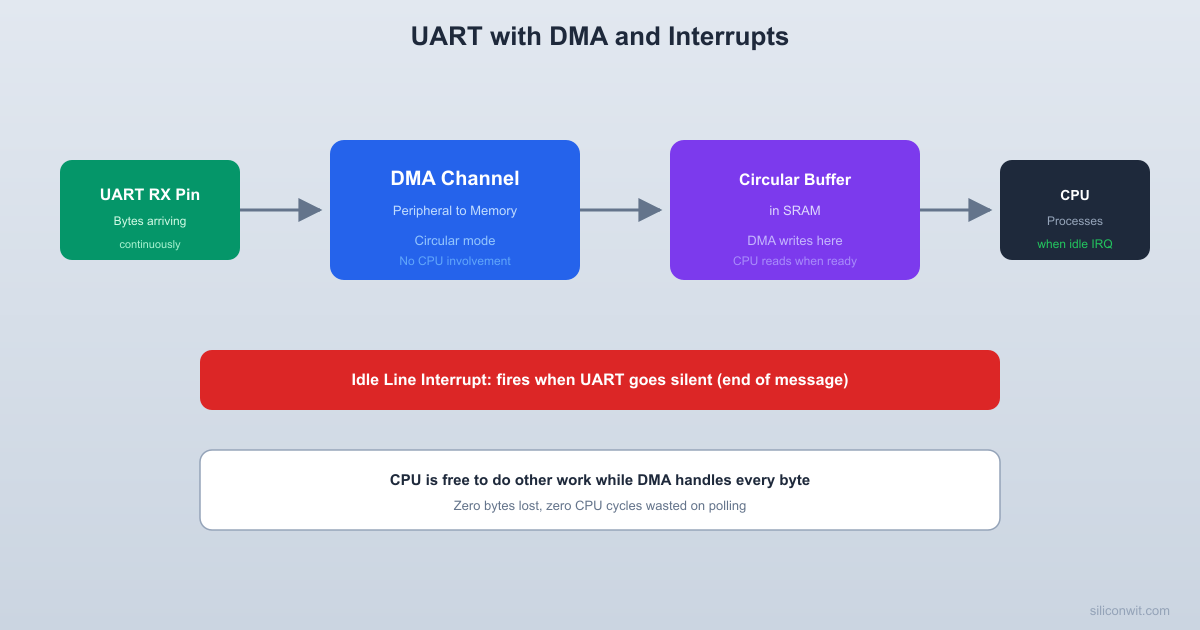
UART Receive with DMA (Circular Buffer)


Why Circular Mode

In normal DMA mode, the transfer stops when CNDTR reaches zero, and you must reconfigure the channel to start again. In circular mode, the DMA controller automatically reloads CNDTR and wraps back to the start of the buffer. Combined with UART idle line detection, this gives you a continuous receive path that never misses a byte and never needs to be restarted.

Implementation

#define RX_BUF_SIZE 256
uint8_t rx_dma_buf[RX_BUF_SIZE];
volatile uint16_t rx_read_pos = 0;
void uart_dma_rx_init(void) {
/* Enable DMA1 clock */
RCC->AHBENR |= RCC_AHBENR_DMA1EN;
/* Configure DMA1 Channel 5 for USART1 RX */
DMA1_Channel5->CCR = 0; /* Disable channel first */
DMA1_Channel5->CPAR = (uint32_t)&USART1->DR; /* Source: USART data reg */
DMA1_Channel5->CMAR = (uint32_t)rx_dma_buf; /* Destination: RAM buffer */
DMA1_Channel5->CNDTR = RX_BUF_SIZE;
DMA1_Channel5->CCR = DMA_CCR_MINC /* Memory increment */
| DMA_CCR_CIRC /* Circular mode */
| DMA_CCR_TCIE /* Transfer complete interrupt */
| DMA_CCR_HTIE; /* Half transfer interrupt */
DMA1_Channel5->CCR |= DMA_CCR_EN; /* Enable channel */
/* Enable USART1 DMA receiver */
USART1->CR3 |= USART_CR3_DMAR;
/* Enable USART1 IDLE line interrupt */
USART1->CR1 |= USART_CR1_IDLEIE;
}

Processing Received Data

uint16_t uart_dma_available(void) {
uint16_t write_pos = RX_BUF_SIZE - DMA1_Channel5->CNDTR;
if (write_pos >= rx_read_pos) {
return write_pos - rx_read_pos;
} else {
return RX_BUF_SIZE - rx_read_pos + write_pos;
}
}
uint8_t uart_dma_read_byte(void) {
uint8_t byte = rx_dma_buf[rx_read_pos];
rx_read_pos = (rx_read_pos + 1) % RX_BUF_SIZE;
return byte;
}
uint16_t uart_dma_read_line(char *dest, uint16_t max_len) {
uint16_t count = 0;
while (uart_dma_available() > 0 && count < max_len - 1) {
char c = (char)uart_dma_read_byte();
if (c == '\n' || c == '\r') {
if (count > 0) break; /* End of line */
continue; /* Skip leading newlines */
}
dest[count++] = c;
}
dest[count] = '\0';
return count;
}

Idle Line Detection

The UART idle line interrupt fires when the RX line has been idle for one frame duration after receiving data. This provides natural message boundary detection.

Idle line detection:
RX line: ____ __ __ __ __ __ ____________
|__| |__| |__|
h e l p \n
<-- data --> <-- idle -->
^
IDLE interrupt
fires here
DMA circular buffer state:
+---+---+---+---+---+---+---+---+
| h | e | l | p |\n | | | |
+---+---+---+---+---+---+---+---+
^ ^
read_pos write_pos
(= 256 - CNDTR)

This is the perfect trigger for “a complete message has arrived” because most serial terminals send commands as a burst of characters followed by silence. You do not need to poll or wait for a specific delimiter; the idle interrupt tells you when the sender has stopped transmitting.

volatile uint8_t rx_data_ready = 0;
void USART1_IRQHandler(void) {
if (USART1->SR & USART_SR_IDLE) {
/* Clear idle flag by reading SR then DR */
(void)USART1->SR;
(void)USART1->DR;
rx_data_ready = 1;
}
}
void DMA1_Channel5_IRQHandler(void) {
if (DMA1->ISR & DMA_ISR_TCIF5) {
DMA1->IFCR = DMA_IFCR_CTCIF5;
/* Buffer wrapped around; data is still valid in circular mode */
}
if (DMA1->ISR & DMA_ISR_HTIF5) {
DMA1->IFCR = DMA_IFCR_CHTIF5;
/* Half buffer filled; useful for double-buffer processing */
}
}

UART Transmit with DMA


volatile uint8_t tx_busy = 0;
void uart_dma_tx_init(void) {
/* DMA1 Channel 4 for USART1 TX */
DMA1_Channel4->CCR = 0;
DMA1_Channel4->CPAR = (uint32_t)&USART1->DR;
DMA1_Channel4->CCR = DMA_CCR_MINC /* Memory increment */
| DMA_CCR_DIR /* Read from memory */
| DMA_CCR_TCIE; /* Transfer complete interrupt */
/* Enable USART1 DMA transmitter */
USART1->CR3 |= USART_CR3_DMAT;
}
void uart_dma_send(const char *data, uint16_t len) {
/* Wait for previous transfer to complete */
while (tx_busy);
tx_busy = 1;
DMA1_Channel4->CCR &= ~DMA_CCR_EN;
DMA1_Channel4->CMAR = (uint32_t)data;
DMA1_Channel4->CNDTR = len;
DMA1_Channel4->CCR |= DMA_CCR_EN;
}
void DMA1_Channel4_IRQHandler(void) {
if (DMA1->ISR & DMA_ISR_TCIF4) {
DMA1->IFCR = DMA_IFCR_CTCIF4;
DMA1_Channel4->CCR &= ~DMA_CCR_EN;
tx_busy = 0;
}
}

Command Parser


#include <string.h>
/* Simple string comparison for first N characters */
static int starts_with(const char *str, const char *prefix) {
return strncmp(str, prefix, strlen(prefix)) == 0;
}
/* Parse integer from string, return pointer to next character */
static const char *parse_int(const char *s, int32_t *out) {
int32_t val = 0;
int neg = 0;
while (*s == ' ') s++;
if (*s == '-') { neg = 1; s++; }
while (*s >= '0' && *s <= '9') {
val = val * 10 + (*s - '0');
s++;
}
*out = neg ? -val : val;
return s;
}
static char tx_buf[512]; /* Transmit buffer for DMA */
void cmd_help(void) {
const char *msg =
"\r\n=== STM32 Command Shell ===\r\n"
"Commands:\r\n"
" help Show this help\r\n"
" pwm <ch> <duty> Set TIM2 channel PWM (0-100%%)\r\n"
" read <port><pin> Read GPIO pin (e.g., read A5)\r\n"
" dump <periph> Dump registers (RCC, GPIOA, TIM2)\r\n"
" reset Software reset\r\n\r\n";
uart_dma_send(msg, strlen(msg));
}
void cmd_pwm(const char *args) {
int32_t channel, duty;
args = parse_int(args, &channel);
args = parse_int(args, &duty);
if (channel < 1 || channel > 4 || duty < 0 || duty > 100) {
const char *err = "Error: pwm <1-4> <0-100>\r\n";
uart_dma_send(err, strlen(err));
return;
}
uint16_t ccr_val = (uint16_t)((TIM2->ARR + 1) * duty / 100);
switch (channel) {
case 1: TIM2->CCR1 = ccr_val; break;
case 2: TIM2->CCR2 = ccr_val; break;
case 3: TIM2->CCR3 = ccr_val; break;
case 4: TIM2->CCR4 = ccr_val; break;
}
int len = snprintf(tx_buf, sizeof(tx_buf),
"PWM CH%ld set to %ld%% (CCR=%u)\r\n",
(long)channel, (long)duty, ccr_val);
uart_dma_send(tx_buf, len);
}
void cmd_read_pin(const char *args) {
while (*args == ' ') args++;
char port_letter = *args++;
int32_t pin;
parse_int(args, &pin);
GPIO_TypeDef *port = NULL;
switch (port_letter) {
case 'A': case 'a': port = GPIOA; break;
case 'B': case 'b': port = GPIOB; break;
case 'C': case 'c': port = GPIOC; break;
}
if (!port || pin > 15) {
const char *err = "Error: read <A-C><0-15>\r\n";
uart_dma_send(err, strlen(err));
return;
}
uint8_t state = (port->IDR >> pin) & 1;
int len = snprintf(tx_buf, sizeof(tx_buf),
"P%c%ld = %d\r\n", port_letter, (long)pin, state);
uart_dma_send(tx_buf, len);
}
void cmd_dump_rcc(void) {
int len = snprintf(tx_buf, sizeof(tx_buf),
"RCC Registers:\r\n"
" CR = 0x%08lX\r\n"
" CFGR = 0x%08lX\r\n"
" APB2ENR= 0x%08lX\r\n"
" APB1ENR= 0x%08lX\r\n"
" AHBENR = 0x%08lX\r\n",
(unsigned long)RCC->CR,
(unsigned long)RCC->CFGR,
(unsigned long)RCC->APB2ENR,
(unsigned long)RCC->APB1ENR,
(unsigned long)RCC->AHBENR);
uart_dma_send(tx_buf, len);
}
void process_command(const char *cmd) {
if (starts_with(cmd, "help")) {
cmd_help();
} else if (starts_with(cmd, "pwm")) {
cmd_pwm(cmd + 3);
} else if (starts_with(cmd, "read")) {
cmd_read_pin(cmd + 4);
} else if (starts_with(cmd, "dump RCC") || starts_with(cmd, "dump rcc")) {
cmd_dump_rcc();
} else if (starts_with(cmd, "reset")) {
NVIC_SystemReset();
} else {
const char *err = "Unknown command. Type 'help' for list.\r\n";
uart_dma_send(err, strlen(err));
}
}

Main Application


int main(void) {
clock_init();
systick_init();
nvic_config();
/* USART1 basic init (baud rate, TX/RX enable) */
uart_init();
/* DMA-based RX and TX */
uart_dma_rx_init();
uart_dma_tx_init();
/* PWM on TIM2 for the 'pwm' command to control */
servo_pwm_init();
cmd_help(); /* Print welcome message */
char cmd_buf[128];
while (1) {
if (rx_data_ready) {
rx_data_ready = 0;
/* Read all available lines */
while (uart_dma_available() > 0) {
uint16_t len = uart_dma_read_line(cmd_buf, sizeof(cmd_buf));
if (len > 0) {
/* Echo the command */
int echo_len = snprintf(tx_buf, sizeof(tx_buf),
"> %s\r\n", cmd_buf);
uart_dma_send(tx_buf, echo_len);
/* Wait for echo to finish before processing */
while (tx_busy);
process_command(cmd_buf);
}
}
}
/* CPU is free for other tasks here */
__WFI(); /* Wait for interrupt (low power idle) */
}
}

Testing the Shell

Connect PA9 to your serial adapter’s RX and PA10 to its TX (cross-connect). Open a terminal at 115200 baud and try these commands:

> help
> pwm 1 50
> pwm 1 100
> read A0
> read C13
> dump RCC
> reset

What You Have Learned


Lesson 4 Complete

Interrupt knowledge:

  • NVIC priority grouping and how preemption vs. sub-priority works
  • Setting interrupt priorities for multiple peripherals
  • Proper interrupt flag clearing sequences

DMA skills:

  • DMA channel assignments and the fixed peripheral-to-channel mapping
  • Circular mode for continuous receive without CPU intervention
  • Normal mode for transmit with completion interrupt
  • DMA configuration registers (CCR, CNDTR, CPAR, CMAR)

UART skills:

  • UART idle line detection for message framing
  • DMA-based receive into circular buffer with no lost bytes
  • DMA-based transmit for non-blocking serial output
  • Command parser architecture for embedded shells

System design:

  • Using __WFI() for low-power idle when no work is pending
  • Separating receive buffering from command processing
  • Building a debugging interface into firmware from the start

Comments

Loading comments...


© 2021-2026 SiliconWit®. All rights reserved.