Displacement, Velocity, Acceleration
Full kinematic profiles across 360 degrees of crank rotation. Switch between angle-domain and time-domain views. See how offset creates asymmetric quick-return motion.
The crank-slider is the most widely used mechanism in engineering: internal combustion engines, reciprocating compressors, hydraulic presses, and packaging machinery all depend on it. This simulator provides complete kinematic and force analysis for any crank-slider configuration, with real-time animation and interactive charts. #CrankSlider #MechanismSimulator #KinematicAnalysis
Open SimulatorDisplacement, Velocity, Acceleration
Full kinematic profiles across 360 degrees of crank rotation. Switch between angle-domain and time-domain views. See how offset creates asymmetric quick-return motion.
Force and Torque Analysis
Apply a constant slider force and observe how crank torque varies through the cycle. Critical for motor sizing, flywheel design, and understanding why reciprocating machines vibrate.
Connecting Rod and Transmission Angles
Monitor the angles that determine mechanism viability. When the transmission angle drops below 40 degrees, the mechanism becomes inefficient. Watch it happen as you push parameter limits.
Mechanical Advantage
See how force multiplication varies continuously through the rotation cycle. At dead centers, mechanical advantage spikes toward infinity: this is the principle behind toggle presses and coining machines.
Real-Time Animation Watch the mechanism move at the RPM you set. Pause at any angle to inspect geometry. Show or hide the crank path, TDC/BDC markers, and dimensional labels. Download the current frame as a PNG.
Seven Analysis Plots Displacement, velocity, acceleration, mechanical advantage, connecting rod angle, transmission angle, and crank torque. All rendered on interactive charts with hover data readout.
A/B Configuration Comparison Save one configuration as Experiment A, change parameters, and run Experiment B. Both datasets overlay on every chart with distinct colors, making parametric studies visual and immediate.
Negative and Positive Offset Slider offset from -50 mm to +50 mm. Offset is what creates quick-return behavior in shapers and presses. Most textbooks only cover the inline case; this simulator shows the full picture.
Professional Downloads Export CSV data (361 data points across all 7 variables), PNG charts, design specifications with manufacturing tolerances, lab report templates, and parametric FreeCAD Python scripts.
The simulator includes three engineering presets that represent real-world applications:
| Preset | Crank | Rod | Offset | Speed | Slider Force |
|---|---|---|---|---|---|
| IC Engine | 40 mm | 160 mm | 0 mm | 60 RPM | 500 N |
| Air Compressor | 30 mm | 120 mm | 0 mm | 90 RPM | 200 N |
| Hydraulic Press | 60 mm | 180 mm | 10 mm | 30 RPM | 800 N |
Each preset configures all parameters to values representative of the application, letting you immediately see how different machines exploit the same mechanism differently.
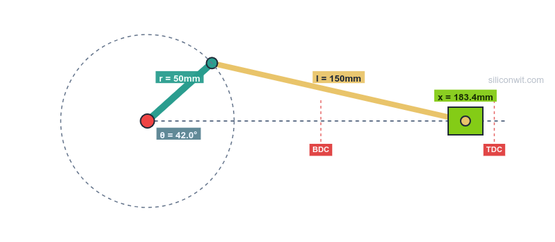
The simulator implements exact analytical solutions (not approximations):
Position:
x = r * cos(theta) + sqrt(l^2 - (r * sin(theta) - e)^2)Velocity:
v = -r * omega * [sin(theta) + cos(theta) * (r * sin(theta) - e) / sqrt(l^2 - (r * sin(theta) - e)^2)]Acceleration:
Let S = r * sin(theta) - e,  Q = sqrt(l^2 - S^2)
a = omega^2 * [-r * cos(theta) + r * sin(theta) * S / Q - r^2 * cos^2(theta) * l^2 / Q^3]
Where r = crank length, l = connecting rod length, e = slider offset, theta = crank angle, and omega = angular velocity in rad/s.
Eight structured experiments are available in the Mechanism Design and Simulation course, each with Python analysis scripts and design questions:
Comments