Six lessons of C, CMake, and manual register configuration have given you deep control over the RP2040. Now consider the alternative: flash MicroPython, open a REPL, type machine.Pin(25, machine.Pin.OUT).toggle(), and the LED blinks. No build system, no compilation, instant feedback. In this lesson you will rebuild the LED brightness controller from Lesson 2 in MicroPython, then compare the two versions line by line. You will see where Python matches C in capability, where it falls short in performance, and how to write C extension modules for the parts that need raw speed. #MicroPython #RapidPrototyping #RP2040
What We Are Building
Rapid Sensor Dashboard
A reimplementation of the Lesson 2 LED brightness controller in MicroPython, extended into a sensor dashboard. The potentiometer controls LED brightness via PWM, the on-chip temperature sensor feeds a moving average, and all readings display on the REPL with formatted output. You will also write PIO programs in Python using the rp2.StateMachine class and benchmark the performance difference between Python and C for the same operations.
Project specifications:
Parameter
Value
Runtime
MicroPython v1.23+ (RP2040 port)
Hardware Access
machine module (Pin, PWM, ADC, I2C, SPI)
PIO in Python
rp2.StateMachine with @rp2.asm_pio decorator
REPL Interface
USB CDC serial at 115200 baud
Benchmark
ADC sampling loop, C versus Python timing comparison
Extension Module
Custom C module compiled into MicroPython firmware
Parts
Reuse existing parts from Lesson 2
Bill of Materials
Ref
Component
Quantity
Notes
1
Raspberry Pi Pico
1
From previous lessons
2
LED + 220 ohm resistor
1
Reuse from Lesson 2
3
10K potentiometer
1
Reuse from Lesson 2
4
Breadboard + jumper wires
1 set
Same setup as Lesson 2
What Is MicroPython?
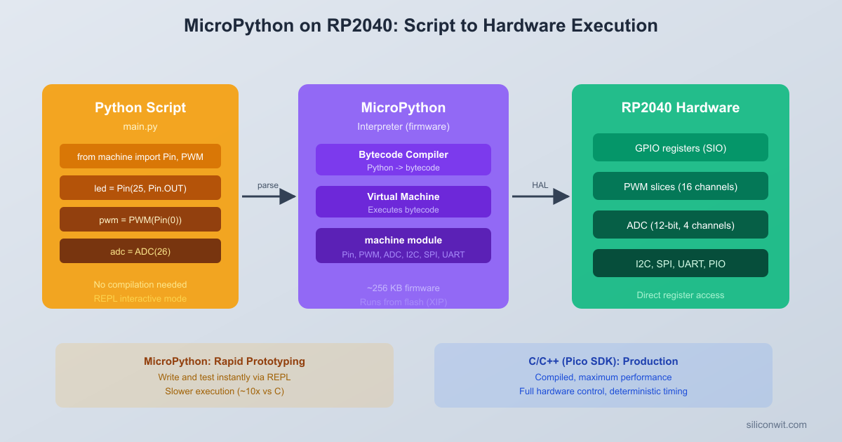
MicroPython is a lean implementation of Python 3 designed to run on microcontrollers. It is not the full CPython interpreter; instead, it compiles Python source code into a compact bytecode format and executes that bytecode on a small virtual machine. The entire runtime, including the compiler, VM, and a subset of the Python standard library, fits within about 256 KB of flash and runs with as little as 16 KB of RAM.
The RP2040 port of MicroPython includes hardware-specific modules that map directly to the chip’s peripherals. The machine module provides classes for Pin, PWM, ADC, I2C, SPI, and Timer. The rp2 module exposes PIO functionality through the StateMachine class and the @rp2.asm_pio decorator. These are not generic abstractions; they give you access to the same hardware registers that the C SDK manipulates, just through a Python API.
The fundamental tradeoff is execution speed versus development speed. A MicroPython loop that reads an ADC and sets a PWM duty cycle runs roughly 10 to 100 times slower than the equivalent C code. For many applications (sensor dashboards, configuration interfaces, test fixtures, protocol prototyping), this performance gap does not matter. The time saved in development, debugging, and iteration often outweighs the runtime cost.
How It Works Internally
MicroPython Execution Pipeline
┌────────────────┐
│ main.py │ Your Python source
│ (on flash) │
└───────┬────────┘
v
┌────────────────┐
│ MicroPython │ Runs on RP2040 itself
│ Compiler │ (not your PC)
└───────┬────────┘
v
┌────────────────┐
│ Bytecode │ Compact instructions
│ (.mpy) │ in RAM
└───────┬────────┘
v
┌────────────────┐
│ MicroPython │ Interprets bytecode
│ VM │ Calls C drivers
└───────┬────────┘
v
┌────────────────┐
│ RP2040 HW │ Same registers as
│ Peripherals │ the Pico C SDK
└────────────────┘
You write a .py file (or type directly into the REPL).
The MicroPython compiler (running on the RP2040 itself) parses the source and emits bytecode.
The MicroPython VM executes the bytecode, calling into C-level hardware drivers when you use machine.Pin, machine.ADC, and so on.
Those C-level drivers interact with the same RP2040 peripheral registers that the Pico SDK uses.
The compilation step happens on the microcontroller, not on your PC. This is why MicroPython needs more flash and RAM than a bare-metal C program, but it also means there is no cross-compilation toolchain to install.
Flashing MicroPython Firmware
The RP2040 uses a UF2 (USB Flashing Format) file to install firmware. MicroPython provides prebuilt UF2 images for the Raspberry Pi Pico.
Download the latest MicroPython UF2 file from micropython.org/download/RPI_PICO. Look for the “Releases” section and pick the latest stable .uf2 file.
Hold the BOOTSEL button on the Pico, then connect the USB cable to your computer. The Pico appears as a USB mass storage device named RPI-RP2.
Drag and drop the .uf2 file onto the RPI-RP2 drive. The Pico will reboot automatically.
The Pico now runs MicroPython. It no longer appears as a mass storage device; instead it presents a USB CDC serial port.
Verifying the Installation
Connect to the serial port using any terminal program. The baud rate is 115200.
Open PuTTY or the Arduino Serial Monitor. Select the COM port that appeared when you plugged in the Pico (check Device Manager if unsure) and set the baud rate to 115200.
You should see the MicroPython REPL prompt:
MicroPython v1.23.0 on 2024-06-02; Raspberry Pi Pico with RP2040
Type "help()" for more information.
>>>
REPL Basics
The REPL (Read-Eval-Print Loop) is an interactive Python shell running directly on the RP2040. Try these commands to confirm hardware access:
>>>import machine
>>> pin = machine.Pin(25, machine.Pin.OUT) # Onboard LED on Pico (non-W)
>>> pin.toggle() # LED turns on
>>> pin.toggle() # LED turns off
>>>import sys
>>> sys.implementation
(name='micropython', version=(1, 23, 0), ...)
Press Ctrl+C to interrupt a running program. Press Ctrl+D for a soft reset, which restarts MicroPython and re-runs main.py if it exists on the filesystem.
The machine Module
The machine module is your primary interface to RP2040 hardware from MicroPython. It provides Python classes that wrap the same peripherals you configured with the C SDK in previous lessons.
Pin
The Pin class controls GPIO configuration and digital I/O.
from machine import Pin
# Output: configure GP15 as a push-pull output
led =Pin(15, Pin.OUT)
led.value(1) # Drive high
led.value(0) # Drive low
led.toggle() # Flip state
# Input: configure GP14 with internal pull-up
button =Pin(14, Pin.IN, Pin.PULL_UP)
state = button.value() # Returns 0 or 1
Compare this with the C SDK equivalent:
/* C SDK: configure GP15 as output, drive high */
gpio_init(15);
gpio_set_dir(15, GPIO_OUT);
gpio_put(15, 1);
/* C SDK: configure GP14 as input with pull-up */
gpio_init(14);
gpio_set_dir(14, GPIO_IN);
gpio_pull_up(14);
bool state =gpio_get(14);
The Python version is more concise because the Pin constructor handles initialization, direction, and pull configuration in a single call. The C version requires separate function calls for each step.
PWM
The PWM class configures a PWM output on any GPIO that supports it.
from machine import Pin, PWM
pwm =PWM(Pin(15)) # Create PWM on GP15
pwm.freq(1000) # Set frequency to 1 kHz
pwm.duty_u16(32768) # 50% duty cycle (range: 0 to 65535)
pwm.duty_u16(0) # Turn off
pwm.deinit() # Release the PWM hardware
In MicroPython, the duty cycle is always specified as a 16-bit value (0 to 65535), regardless of the underlying PWM resolution. The runtime maps this to the appropriate hardware wrap and level values. In C, you work directly with the slice’s wrap value and set the compare level explicitly.
ADC
The ADC class reads from the RP2040’s 12-bit analog-to-digital converter.
from machine importADC
pot =ADC(26) # ADC on GP26 (channel 0)
raw = pot.read_u16() # Returns 0 to 65535 (scaled from 12-bit)
The structure mirrors the C firmware from Lesson 2 almost exactly. Here is a side-by-side comparison of the key operations:
Operation
C SDK
MicroPython
Initialize ADC
adc_init(); adc_gpio_init(26);
pot = ADC(26)
Read ADC
adc_select_input(0); adc_read();
pot.read_u16()
Configure PWM
5 lines (function, divider, wrap, level, enable)
PWM(Pin(15)); pwm.freq(1000)
Set duty cycle
pwm_set_chan_level(slice, chan, level)
led_pwm.duty_u16(value)
Temperature formula
Same formula, manual float math
Same formula, Python float
Print output
printf(...)
print("...".format(...))
Delay
sleep_ms(200)
time.sleep_ms(50)
The C version requires about 90 lines including headers, defines, and helper functions. The MicroPython version achieves the same result in about 55 lines. More importantly, you can modify the MicroPython version on the fly: change the filter size, adjust the print format, add a new sensor, all without recompiling or reflashing.
C SDK vs MicroPython Development
┌─────────────────┐ ┌──────────────────┐
│ C SDK Workflow │ │ MicroPython │
│ │ │ Workflow │
│ Edit main.c │ │ Edit main.py │
│ │ │ │ │ │
│ cmake + make │ │ (no build step) │
│ (~30 sec build)│ │ │
│ │ │ │ Copy to Pico │
│ UF2 flash or │ │ (instant) │
│ SWD upload │ │ │ │
│ (~5 sec) │ │ Ctrl+D reboot │
│ │ │ │ (<1 sec) │
│ Test │ │ Test │
│ │ │ │
│ Cycle: ~40 sec │ │ Cycle: ~3 sec │
└─────────────────┘ └──────────────────┘
10-100x faster execution 10x faster iteration
PIO in MicroPython
One of the most powerful features of MicroPython on the RP2040 is direct access to the Programmable I/O subsystem. In Lesson 3 you wrote a WS2812B driver as a .pio assembly file and compiled it with the SDK build system. In MicroPython, you write the PIO program directly in Python using the @rp2.asm_pio decorator.
PIO Assembly in Python
The @rp2.asm_pio decorator transforms a Python function into a PIO program. Each PIO instruction is written as a Python function call inside the decorated function. The decorator compiles these into the same 16-bit instruction words that the PIO hardware executes.
Here is the WS2812B driver rewritten in MicroPython PIO:
jmp("bitloop") .side(1) [T2 -1]# Bit=1: stay high T2 more, loop
label("do_zero")
nop() .side(0) [T2 -1]# Bit=0: pin low for T2
wrap()
# Create a state machine on PIO0, state machine 0, at 8 MHz, on GP2
sm = rp2.StateMachine(0, ws2812,freq=8_000_000,sideset_base=Pin(2))
sm.active(1)
NUM_PIXELS=8
defput_pixel(grb):
"""Send a 24-bit GRB value to the state machine."""
sm.put(grb <<8,24)
defwheel(pos):
"""Color wheel: input 0-255, output (g, r, b) packed as GRB integer."""
if pos <85:
return (pos *3) <<16| (255- pos *3) <<8|0
elif pos <170:
pos -=85
return (255- pos *3) <<16|0<<8| (pos *3)
else:
pos -=170
return0<<16| (pos *3) <<8| (255- pos *3)
# Rainbow chase animation
t =0
whileTrue:
for i inrange(NUM_PIXELS):
hue = (t *3+ i *32) &0xFF
put_pixel(wheel(hue))
time.sleep_ms(50)
t +=1
Mapping .pio Syntax to Python Decorator Syntax
The table below shows how each element of the .pio file from Lesson 3 translates to the Python decorator:
.pio File Syntax
MicroPython Decorator Syntax
.side_set 1
sideset_init=rp2.PIO.OUT_LOW
.wrap_target
wrap_target() (called inside the function)
.wrap
wrap() (called inside the function)
out x, 1 side 0 [2]
out(x, 1) .side(0) [2]
jmp !x do_zero side 1 [1]
jmp(not_x, "do_zero") .side(1) [1]
nop side 0 [4]
nop() .side(0) [4]
.define public T1 2
T1 = 2 (regular Python variable)
Autopull config in C init code
autopull=True, pull_thresh=24 in decorator
The decorator parameters (sideset_init, out_shiftdir, autopull, pull_thresh) replace the configuration that you would set in C using sm_config_set_sideset_pins(), sm_config_set_out_shift(), and similar functions.
The rp2.StateMachine() constructor replaces the C initialization sequence: it claims a PIO block and state machine, loads the program, sets the clock divider (via the freq parameter), and configures the pin mappings, all in a single call.
C vs Python: Side-by-Side Comparison
To quantify the performance difference, here is a benchmark that counts how many ADC samples each language can read in one second.
MicroPython Benchmark
benchmark_mp.py
from machine importADC
import time
adc =ADC(26)
start = time.ticks_us()
count =0
while count <10000:
adc.read_u16()
count +=1
elapsed = time.ticks_diff(time.ticks_us(), start)
samples_per_sec = count *1_000_000// elapsed
print("MicroPython: {} samples in {} us".format(count, elapsed))
printf("C SDK: 100000 samples in %llu us\n", elapsed);
printf("Rate: %lu samples/sec\n", rate);
while (1) tight_loop_contents();
return0;
}
Results Comparison
Metric
C SDK
MicroPython
Ratio
Lines of code (full project)
~90
~55
1.6x fewer in Python
Build time
~5 seconds (cmake + make)
0 (no build step)
Instant
Flash usage
~40 KB (.uf2)
~650 KB (firmware) + ~2 KB (script)
16x more
RAM usage
~8 KB
~60 KB (interpreter + heap)
7.5x more
ADC loop speed
~480,000 samples/sec
~18,000 samples/sec
~27x faster in C
Development time (this project)
~30 minutes
~10 minutes
3x faster in Python
The C version is dramatically faster for tight loops. The MicroPython version is dramatically faster to write, test, and modify. Neither is universally better; the right choice depends on what the project requires.
Writing a C Extension Module
When a specific function in your MicroPython project becomes a performance bottleneck, you can write it in C and compile it into the MicroPython firmware. This gives you Python-level convenience for most of the code and C-level speed for the critical path.
Module Structure Overview
A C extension module for MicroPython consists of three parts: the C function implementation, a module definition table, and a registration macro. Here is a minimal example that provides a fast ADC averaging function.
modfastadc.c
#include"py/runtime.h"
#include"py/obj.h"
#include"hardware/adc.h"
/* C implementation: read N ADC samples and return the average */
STATIC mp_obj_tfastadc_average(mp_obj_tn_obj) {
int n =mp_obj_get_int(n_obj);
if (n <=0|| n >10000) {
mp_raise_ValueError(MP_ERROR_TEXT("n must be 1 to 10000"));
To compile this into MicroPython, you clone the MicroPython repository, place your module source in the ports/rp2/ directory (or use the USER_C_MODULES mechanism), and rebuild:
The build produces a new .uf2 file that includes your C module. Flash it to the Pico using the same BOOTSEL procedure, and your module becomes importable:
>>>import fastadc
>>>from machine importADC
>>> adc =ADC(26)
>>> avg = fastadc.average(1000) # 1000 samples averaged in C, returned to Python
>>>print(avg)
This approach is useful for signal processing routines, fast sampling loops, or any computation where the Python overhead is unacceptable. For most application logic, pure MicroPython is fast enough.
File Management with Thonny and mpremote
MicroPython exposes a small filesystem on the Pico’s flash memory (using littlefs). You can store Python scripts, configuration files, and data logs on this filesystem. Two tools are commonly used to manage files.
Thonny IDE
Thonny is a beginner-friendly Python IDE with built-in MicroPython support. Install it from thonny.org or via your system package manager.
Open Thonny and go to Tools > Options > Interpreter.
Select MicroPython (Raspberry Pi Pico) from the interpreter dropdown.
Select the correct serial port.
The bottom pane becomes the Pico’s REPL. The file browser (View > Files) shows both your local filesystem and the Pico’s filesystem side by side.
To upload a script, right-click a local file and select Upload to / (or drag it to the Pico file list).
Click the green Run button to execute the current script on the Pico.
Thonny is excellent for interactive development. You can edit a script, save it to the Pico, and run it immediately without leaving the IDE.
mpremote (Command-Line Tool)
For a terminal-based workflow, mpremote is the official MicroPython command-line tool. Install it with pip:
Terminal window
pipinstallmpremote
Common operations:
Terminal window
# Connect to the REPL
mpremoteconnectautorepl
# Copy a file to the Pico
mpremoteconnectautocpmain.py:main.py
# Copy a file from the Pico to your PC
mpremoteconnectautocp:main.py./main_backup.py
# List files on the Pico
mpremoteconnectautols
# Run a script without saving it to the Pico
mpremoteconnectautorunbenchmark_mp.py
# Remove a file from the Pico
mpremoteconnectautorm:old_script.py
# Soft reset the Pico
mpremoteconnectautoreset
The mpremote tool is scriptable, making it useful for automated testing and deployment workflows. You can chain commands:
Terminal window
# Upload, reset, and connect to REPL in one command
mpremoteconnectautocpmain.py:main.py+reset+repl
Filesystem Layout
A typical MicroPython project on the Pico looks like this:
boot.py
main.py
Directorylib/
ws2812b_pio.py
sensor_utils.py
boot.py runs first on every boot (used for low-level configuration like setting the CPU frequency). main.py runs immediately after boot.py and is where your application code goes. The lib/ directory is on the module search path, so any .py file placed there can be imported by name.
When to Use MicroPython vs C
Choosing between MicroPython and C is not an all-or-nothing decision. Many projects use MicroPython for prototyping and switch to C only when performance requirements demand it. Others ship MicroPython in production because the application never needs the speed that C provides.
Decision Framework
Factor
Favor MicroPython
Favor C SDK
Timing requirements
Tolerances above 1 ms
Microsecond or sub-microsecond precision
Iteration speed
Rapid prototyping, frequent changes
Stable requirements, infrequent changes
Code complexity
Logic-heavy (parsers, state machines, menus)
Compute-heavy (DSP, motor control loops)
Flash/RAM budget
Plenty of room (RP2040 has 2 MB flash, 264 KB RAM)
Memory-constrained designs
Team experience
Team knows Python, new to embedded
Team knows C, comfortable with SDK
Debugging
REPL makes interactive debugging trivial
Printf debugging or SWD with GDB
Power consumption
Not critical (USB-powered prototypes)
Battery-powered, need deep sleep optimization
PIO programs
Same capability (decorator syntax)
Same capability (.pio files)
Hybrid Approach
The C extension module technique from the previous section enables a hybrid approach: write the application in MicroPython and drop into C only for the functions that need it. This is particularly effective for projects where 90% of the code is configuration, user interface, or network communication (all fine in Python) and 10% is a tight sampling loop or signal processing routine (better in C).
PIO programs have the same performance in both languages because the PIO hardware executes independently of the CPU. A WS2812B driver written with @rp2.asm_pio produces identical timing to the .pio file compiled with the C SDK. The only difference is how you configure and start the state machine, which is a one-time cost at initialization.
Experiments
Try these modifications to deepen your understanding of MicroPython on the RP2040.
Experiment 1: I2C Sensor Integration
Connect an I2C sensor (such as a BMP280 pressure/temperature sensor or an SSD1306 OLED display) to GP4 (SDA) and GP5 (SCL). Use machine.I2C(0, sda=Pin(4), scl=Pin(5), freq=400000) to initialize the bus, then scan for devices with i2c.scan(). Write a driver class that reads sensor data and displays it alongside the potentiometer and temperature readings.
Experiment 2: Flash Data Logger
Use MicroPython’s built-in filesystem to log ADC readings to a CSV file on the Pico’s flash. Open a file with f = open("log.csv", "a") and write timestamped readings. Add a button on GP14 that starts and stops logging. Be mindful of flash wear: buffer writes and flush periodically rather than writing every sample individually.
Experiment 3: Interactive REPL Menu
Build a command-line menu system that accepts single-character commands from the REPL. For example: f to change the PWM frequency, d to set a duty cycle directly, t to print the temperature, b to run the ADC benchmark, and q to quit. Use sys.stdin.read(1) in a non-blocking fashion with select.poll() to check for input without halting the main loop.
Experiment 4: PIO Frequency Counter
Write a PIO program that counts rising edges on an input pin over a fixed time window. Use one state machine to generate a gating signal (high for exactly 1 second, then trigger an IRQ) and a second state machine to count pulses during that window. This technique can measure frequencies from a few Hz up to several MHz with cycle-exact accuracy.
Comments