A diode is the simplest semiconductor device: it allows current to flow in one direction and blocks it in the other. This one-way behavior is the foundation of rectifiers that convert AC to DC, protection circuits that guard your MCU against voltage spikes, and voltage references that keep critical circuits stable. Every relay driver, every motor controller, and every power supply you will encounter uses diodes. #AnalogElectronics #Diodes #CircuitProtection
How a Diode Works
A diode is made from a junction of two types of semiconductor material: P-type (positive, with extra “holes”) and N-type (negative, with extra electrons). The boundary between them is called the PN junction.
The One-Way Valve Analogy
Think of a diode as a check valve in a water pipe. Water (current) flows freely in one direction but is blocked in the other. The valve requires a small amount of pressure (voltage) to open. Below that threshold, even the “forward” direction is blocked.
Forward Bias
When the anode (P-side) is more positive than the cathode (N-side) by at least the forward voltage , the diode conducts. For a silicon diode, . For a Schottky diode, . For an LED, ranges from about 1.8V (red) to 3.3V (blue/white).
In forward bias, the diode drops a roughly constant voltage regardless of how much current flows through it (within its rating). This is different from a resistor, where the voltage drop scales with current.
Reverse Bias
When the cathode is more positive than the anode, the diode blocks current. Only a tiny leakage current (typically nanoamps for silicon diodes) flows in this state. The diode can withstand reverse voltage up to its rated reverse breakdown voltage (). Beyond that, the diode breaks down and current flows uncontrollably, usually destroying the device.
The Diode Equation (Optional)
The current through a diode is described by the Shockley diode equation:
Where:
= reverse saturation current (typically A for silicon)
= voltage across the diode
= ideality factor (1 to 2)
= thermal voltage ( at room temperature)
For practical circuit design, you rarely need this equation. The approximation “0.7V drop when conducting, no current when reverse biased” handles most situations.
Common Diode Types
Type
Forward Voltage
Key Use
Common Part
Silicon rectifier
0.7V
Power supply rectification
1N4007
Schottky
0.2 to 0.45V
Low-loss rectification, flyback protection
1N5819
Zener
Operates in reverse breakdown
Voltage regulation, clamping
Various (3.3V, 5.1V, etc.)
LED
1.8 to 3.3V
Light output, indicators
Various colors
Signal diode
0.7V
Small signal switching, demodulation
1N4148
Rectifier Circuits
Rectifiers convert alternating current (AC) to direct current (DC). This is the first stage of every AC power supply.
Half-Wave Rectifier
The simplest rectifier uses a single diode. During the positive half-cycle of the AC input, the diode conducts and the output follows the input (minus the 0.7V diode drop). During the negative half-cycle, the diode blocks and the output is zero.
[D1] 1N4007
AC in o----->|-------+---o +Vout
|
[C1] === 470uF
(filter) |
|
AC in o--------------+---o GND
D1 conducts on positive half-cycle
C1 smooths pulsating DC output
Vout = Vpeak - 0.7V (diode drop)
The output is pulsating DC. Adding a filter capacitor smooths the pulses into a more stable DC voltage with some residual ripple.
Ripple voltage for a half-wave rectifier with capacitor filter:
Where is the AC frequency (50 or 60 Hz) and is the filter capacitor value.
Full-Wave Bridge Rectifier
A bridge rectifier uses four diodes arranged so that both halves of the AC cycle produce output current. This doubles the effective frequency, reducing ripple and making filtering easier.
D1 D3
AC ~──┬──►──┬──►──┬── +Vout
│ │ │
│ │ ├── C (filter)
│ │ │
AC ~──┴──►──┴──►──┴── GND
D2 D4
The output voltage is the AC peak minus two diode drops (about 1.4V for silicon diodes). The ripple formula becomes:
The factor of 2 in the denominator means a bridge rectifier produces half the ripple of a half-wave rectifier for the same capacitor value.
Zener Diode Voltage Regulation
A Zener diode is designed to operate in reverse breakdown. Unlike a regular diode that is damaged by reverse breakdown, a Zener diode maintains a stable voltage across it (the Zener voltage, ) when reverse biased beyond .
Zener Regulator Circuit
Vin ──── R (series) ──┬── Vout = Vz
│
├── Zener (cathode to Vin side)
│
└── GND
The series resistor limits current through the Zener. The resistor value is calculated as:
Where is the Zener bias current (typically 5 to 20 mA for stable regulation) and is the current drawn by whatever is connected to .
Zener Limitations
Zener regulators are simple but inefficient. The series resistor wastes power as heat, and the Zener itself dissipates power:
For loads drawing more than about 50 mA, a dedicated voltage regulator IC (Lesson 6) is a much better choice. Zener diodes are still useful for:
Voltage clamping (limiting a signal to a safe range)
Voltage references in precision circuits
Overvoltage protection on input pins
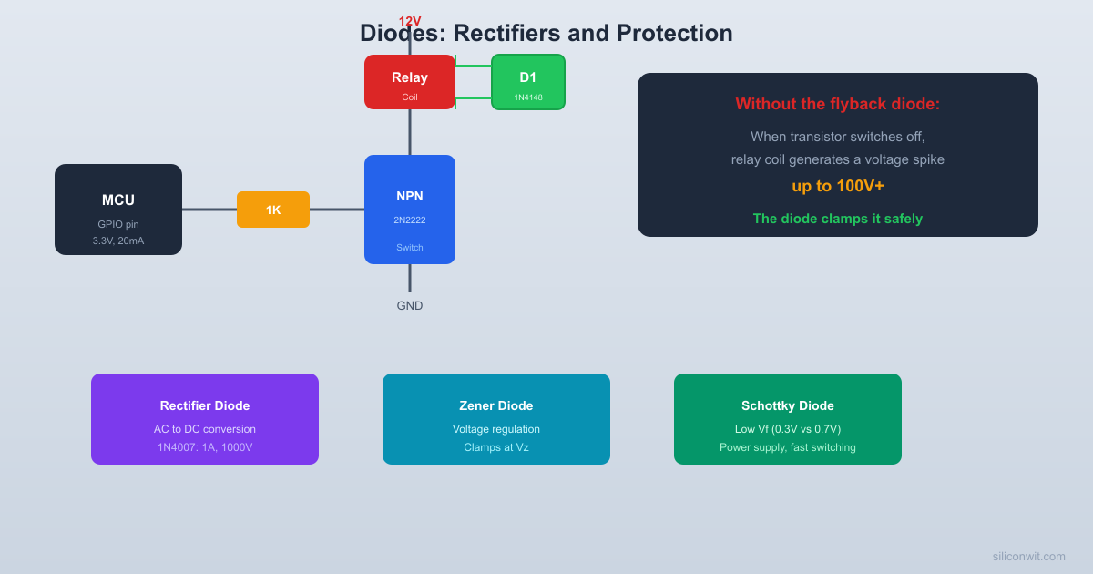
Flyback Protection
When current through an inductive load (motor, relay, solenoid) is suddenly interrupted, the inductor produces a large voltage spike in the opposite direction. Recall from Lesson 2:
If is very large (current dropping to zero in microseconds), the voltage spike can reach hundreds of volts, enough to destroy a transistor switch or an MCU GPIO pin.
The Flyback Diode
A diode placed in reverse (cathode to positive supply, anode to ground side of the inductor) across the inductive load provides a safe path for the current when switching stops. The inductor’s energy dissipates through the diode instead of creating a destructive voltage spike.
+5V
|
+-------+
| |
Relay [D1] 1N4007 (flyback)
Coil cathode at top
| |
+-------+
|
+---> Collector (2N2222)
|
GPIO --[Rb]-- Base
|
GND (Emitter)
D1 is reverse biased during normal
operation. When transistor turns off,
D1 clamps the inductive spike.
This is not optional. Every inductive load driven by a transistor or MOSFET switch must have a flyback diode. The 1N4007 is a common choice for relays and small motors. For faster switching applications, a Schottky diode (1N5819) is preferred because its lower forward voltage and faster recovery time clamp the spike more effectively.
ESD and Reverse Polarity Protection
Reverse Polarity Protection
A diode in series with the power input prevents damage if the power supply is connected backwards:
[D1]
Battery + o--->|---+--- Vcc (to circuit)
|
[C1] === 100uF
|
Battery - o--------+--- GND (to circuit)
Correct polarity: D1 conducts
Reversed polarity: D1 blocks
Use Schottky for lower 0.3V drop
The diode drops 0.7V from the supply, which is acceptable in many applications. For lower loss, use a Schottky diode (0.3V drop) or a P-channel MOSFET as a reverse polarity switch (millivolt drop).
TVS (Transient Voltage Suppressor) Diodes
TVS diodes are specialized Zener-like devices designed to absorb large transient voltage spikes (from ESD, lightning, or switching events). They clamp the voltage to a safe level within nanoseconds. You will find TVS diodes on USB ports, Ethernet ports, and any connector exposed to the outside world on production PCBs.
Practical Build: Half-Wave Rectifier and Flyback Protection
Components Needed
Component
Quantity
Notes
Breadboard
1
From previous lessons
1N4007 diodes
4
General purpose rectifier
Zener diode 5.1V
1
1/2 watt rating
Electrolytic capacitor 470
1
16V or higher
Resistors: 220, 1k, 10k ohm
2 each
1/4 watt
LED (red)
2
For indicators
5V power source
1
USB or battery
Digital multimeter
1
DC voltage mode
Small relay (5V coil, optional)
1
For flyback demo
NPN transistor 2N2222 (optional)
1
For relay driver
Jumper wires
Several
Male-to-male
Circuit 1: Half-Wave Rectifier with Filter
Since most beginners do not have an AC source, we will simulate one using a function generator or by manually toggling a connection. If you have a small transformer (e.g., 9V AC from a wall adapter with exposed secondary), you can use that.
For the breadboard version without AC:
Build the rectifier
Connect a 1N4007 diode from the positive rail to a row. The anode (no stripe) faces the positive rail. The cathode (stripe end) faces the output.
Add the filter capacitor
Connect a 470 electrolytic capacitor from the diode’s cathode to ground. Positive leg to the cathode side, negative leg to ground.
Add a load
Connect an LED with a 220 ohm resistor from the capacitor’s positive side to ground.
Connect and disconnect power
Rapidly connect and disconnect the 5V supply. This simulates a crude AC input. The LED should stay lit briefly after disconnection because the capacitor holds its charge. With a true AC source, the LED would stay lit continuously, with the capacitor smoothing the pulsating DC.
Measure the output voltage
With power connected, measure across the capacitor. You should see approximately 4.3V (5V minus the 0.7V diode drop).
Reverse the diode
Flip the diode and reconnect power. The LED should not light because the diode blocks current in this direction. This demonstrates the one-way property of the diode.
Circuit 2: Zener Voltage Regulator
Build the Zener circuit
Connect a 1k ohm resistor from the 5V rail to a row. Connect a 5.1V Zener diode from that row to ground, with the cathode (stripe) facing the resistor (toward 5V).
Measure the Zener voltage
Place your multimeter across the Zener diode. You should read approximately 5.1V. Wait, that does not seem right with a 5V supply. The Zener needs about 0.1V of headroom across the resistor, so with only 5V in, the regulation may be marginal.
Increase the supply voltage
If you have a 9V battery, use that instead. Now the resistor drops approximately 3.9V (), and the Zener maintains a stable 5.1V output. Calculate the Zener current: .
Add a load
Connect an LED with a 220 ohm resistor across the Zener output. The output voltage should remain close to 5.1V as long as the total current does not exceed what the series resistor can supply.
Verify regulation
Measure the output voltage with and without the LED load. The voltage should remain stable (within 0.1 to 0.2V). This is voltage regulation in action.
Circuit 3: Flyback Diode Demonstration (Optional)
If you have a small relay and a transistor:
Build the relay driver
Connect the relay coil between 5V and the collector of a 2N2222 NPN transistor. Connect the emitter to ground. Connect a 1k resistor from a 3.3V or 5V signal (simulating a GPIO pin) to the base.
Without flyback diode
Toggle the base signal on and off. If you have an oscilloscope on the collector, you will see a large negative voltage spike (potentially tens of volts) when the relay turns off. This spike travels back to whatever is driving the base, potentially damaging it.
Add the flyback diode
Place a 1N4007 diode across the relay coil with the cathode connected to the +5V side and the anode to the collector side. The diode is reverse-biased during normal operation (no current through it), but when the relay switches off, the spike forward-biases the diode, providing a safe discharge path.
Observe the difference
With the flyback diode in place, the collector voltage spike is clamped to about 5.7V (5V + 0.7V diode drop) instead of spiking to destructive levels.
Verification Checklist
Measurement
Expected Value
Your Measurement
Half-wave rectifier output (5V input)
~4.3V
________
Reversed diode output
~0V
________
Zener output (9V input, no load)
~5.1V
________
Zener output (9V input, LED load)
~5.0V
________
Collector spike without flyback diode
>20V transient
________
Collector spike with flyback diode
~5.7V
________
Common Mistakes
Watch Out For These
Diode installed backwards: A reversed diode blocks current when you expect it to flow. Always check the stripe marking (cathode) against your circuit diagram.
Forgetting the flyback diode: This is the number one cause of transistor failure in hobbyist projects. If you are switching anything with a coil (relay, motor, solenoid), add a flyback diode. Period.
Zener confusion: A Zener diode looks like a regular diode. Label it or keep it in its labeled bag. Using a regular diode where you need a Zener (or vice versa) produces unexpected behavior.
Exceeding Zener power rating: If the Zener dissipates more power than its rating (typically 0.5W or 1W for through-hole parts), it overheats. Calculate: .
How This Connects to Embedded Systems
Diodes Protect Your MCU
Flyback diodes on relay and motor drivers: The STM32 sensor interfacing course uses a flyback diode when driving a relay from a GPIO pin through a transistor. Without it, the voltage spike when the relay de-energizes can destroy the transistor and damage the MCU pin.
Reverse polarity protection: Adding a Schottky diode at the power input of your custom board prevents damage if someone plugs the battery in backwards.
Voltage clamping on inputs: Zener diodes or TVS diodes on external input pins protect the MCU from overvoltage events. Many MCU inputs are rated for 3.3V or 5V maximum, and a transient spike can permanently damage the input buffer.
Power supply rectification: If your project runs from an AC adapter, a bridge rectifier converts AC to DC before the voltage regulator. Understanding the diode drop and ripple calculation lets you select the right transformer and filter capacitor.
LED indicator circuits: Every status LED on a PCB has a diode (the LED itself) and a current-limiting resistor. The forward voltage of the LED color determines the resistor value.
Summary
Concept
Key Point
Remember
Forward bias
Diode conducts when
Silicon: 0.7V, Schottky: 0.3V, LED: 1.8 to 3.3V
Reverse bias
Diode blocks current
Leakage is nanoamps for silicon
Half-wave rectifier
Single diode, pulsating DC output
Output =
Bridge rectifier
Four diodes, full-wave DC output
Output = , half the ripple
Zener regulation
Stable voltage in reverse breakdown
Simple but inefficient for high currents
Flyback diode
Clamps inductive kick
Always use with relays, motors, solenoids
Reverse polarity protection
Series diode blocks wrong polarity
Schottky for lower loss
Next lesson: transistors. With diodes you learned about one PN junction. A transistor has two junctions, and this gives it the ability to switch and amplify, making it the foundation of every digital and analog circuit.
Comments