A microcontroller GPIO pin can typically source or sink 10 to 25 mA. That is enough to light an LED but nowhere near enough to drive a motor, relay, solenoid, or high-power LED strip. Transistors solve this problem by using a small control signal to switch a much larger current. They are also the foundation of amplifiers, logic gates, and nearly every active circuit in electronics. #AnalogElectronics #Transistors #EmbeddedSystems
Two Families: BJT and MOSFET
There are two main families of transistors used in hobbyist and embedded circuits.
BJT (Bipolar Junction Transistor)
Current-controlled device with three terminals: Base, Collector, Emitter. A small base current controls a much larger collector current. Common types: NPN (2N2222, BC547) and PNP (2N2907, BC557). Good for simple switching and analog amplification at low to medium currents.
MOSFET (Metal-Oxide-Semiconductor FET)
Voltage-controlled device with three terminals: Gate, Drain, Source. A voltage on the gate controls drain-source current with virtually zero gate current. Common types: N-channel (2N7000, IRFZ44N) and P-channel (IRF9540). Excellent for power switching because they have very low on-resistance.
For most embedded switching applications (driving motors, relays, LED strips), MOSFETs are the modern choice because they are more efficient and easier to drive from logic-level pins. BJTs are still widely used for signal-level switching, amplification, and in legacy circuits.
BJT Fundamentals
NPN Transistor as a Switch
An NPN transistor has three regions of operation:
Region
Base-Emitter
Collector-Emitter
Behavior
Cutoff
Open circuit
No current flows, switch is OFF
Active
Controlled by
Linear amplification region
Saturation
, base current high
Full on, switch is ON
For switching applications, we want the transistor to be either fully OFF (cutoff) or fully ON (saturation). We avoid the active region for switching because it wastes power.
The Water Valve Analogy
Think of an NPN transistor as a water valve:
The base is the valve handle. A small twist (small current) opens the valve.
The collector is where water enters (from the load and supply).
The emitter is where water exits (to ground).
A small force on the handle controls a large flow of water through the valve.
+5V
|
Motor
(load)
|
+---> Collector (2N2222)
|
GPIO ---[Rb] 470R --- Base
|
GND <--- Emitter
GPIO HIGH: base current flows,
transistor saturates, motor runs
GPIO LOW: no base current,
transistor off, motor stops
(Add flyback diode across motor!)
Base Resistor Calculation
The base resistor limits current into the base to prevent damage. For an NPN transistor switching a load:
Where:
= voltage from the MCU pin (3.3V or 5V)
= base-emitter voltage (approximately 0.7V)
= required base current
The required base current depends on the collector current and the transistor’s current gain ( or ):
For reliable saturation, use a base current 3 to 10 times the minimum calculated value (overdrive the base).
Worked Example: Driving a Relay from a 3.3V GPIO
A relay coil draws 70 mA at 5V. The 2N2222 has a minimum of 75 (check the datasheet, not the typical value).
Minimum base current:
For reliable saturation, use 5x overdrive:
Base resistor:
Use a standard 470 ohm or 560 ohm resistor. The GPIO pin sources about 5 mA, well within the 25 mA limit of most MCU pins.
Do not forget the flyback diode across the relay coil (see Lesson 3).
PNP Transistors
A PNP transistor is the complement of NPN. Current flows from emitter to collector, and the base current flows out of the base. PNP transistors are used for high-side switching (connecting the load between the supply and the transistor, with the transistor switching the ground path). The same principles apply, but the voltages are inverted.
MOSFET Fundamentals
N-Channel MOSFET as a Switch
A MOSFET is controlled by voltage, not current. The key parameter is the gate threshold voltage , below which the MOSFET is off.
Parameter
Meaning
Gate-source voltage to start turning on (typically 1 to 4V)
Drain-source resistance when fully on (milliohms to ohms)
(max)
Maximum continuous drain current
For a MOSFET to be fully ON, you need significantly above . This is where “logic-level MOSFETs” become important.
Designed to turn fully on with 3.3V or 5V gate drive. The is low (around 1 to 2V), and full enhancement is reached at 3.3V to 4.5V. Examples: IRLZ44N, IRL540N, 2N7000.
These can be driven directly from an MCU GPIO pin without any additional circuitry (other than a gate resistor).
Requires 10V or more on the gate to fully turn on. Examples: IRF540, IRFZ44N. These cannot be driven directly from a 3.3V MCU pin. You would need a gate driver IC or a BJT level-shifting stage.
The IRFZ44N has of 2 to 4V, but this is just the threshold. Full turn-on (low ) requires .
Gate Resistor
Unlike a BJT, the MOSFET gate draws virtually zero DC current. However, the gate is a capacitor (), and charging it requires a pulse of current. A small gate resistor (100 to 1k ohm) limits the inrush current from the GPIO pin and prevents ringing:
For slow switching (less than 1 kHz), 1k ohm is fine. For fast PWM (10 kHz+), use 100 to 220 ohm for faster gate charging.
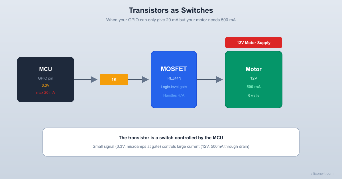
Worked Example: MOSFET Motor Driver
An N-channel MOSFET (IRLZ44N) driving a small DC motor that draws 500 mA at 12V, controlled by a 3.3V GPIO pin.
Check the datasheet:
= 1 to 2V (logic-level, good)
at : approximately 0.04 ohm
max: 47A (way more than we need)
Power dissipated in the MOSFET:
This is negligible. A BJT in the same application would dissipate:
Ten times more. This is why MOSFETs are preferred for power switching.
Circuit:
+12V ──┬── Motor ──┬── Drain (IRLZ44N)
│ │
│ Flyback │
│ Diode │
│ ◄──── │
│ │
└───────────┤
│
GPIO ── 220Ω ─── Gate
│
GND──Source
│
Pull-down 10k──┘
The 10k pull-down resistor on the gate ensures the MOSFET stays OFF when the GPIO pin is floating (during MCU boot, reset, or if the GPIO is set to high-impedance input mode).
BJT as an Amplifier
While switching is the most common use in embedded systems, understanding BJT amplification helps you design sensor signal conditioning circuits.
Common-Emitter Amplifier
+Vcc
|
[Rc] 4.7K (collector R)
|
Vout --+ Collector
|
Vin --[C]--[Rb]-- Base (2N2222)
|
Emitter
|
[Re] 1K (emitter R)
|
GND
Voltage gain: Av = -Rc / Re
Negative sign = output inverted
In the active region, a BJT amplifies the base signal:
A common-emitter amplifier inverts and amplifies a small input signal. The voltage gain depends on the collector and emitter resistors:
Where is the collector resistor and is the emitter resistor. The negative sign indicates phase inversion.
For embedded applications, op-amps (Lesson 5) are usually a better choice for amplification because they are easier to design with and provide more predictable performance. But understanding BJT amplification gives you insight into how op-amps work internally.
Biasing
For the amplifier to work in the active region, the transistor must be properly biased (DC operating point set in the middle of its operating range). This requires careful resistor selection. A voltage divider bias network is the most stable configuration:
We will not build a full amplifier circuit in this lesson, but understanding these concepts will help you in Lesson 5 when we study op-amps, which are essentially optimized transistor amplifiers on a single chip.
Practical Build: Transistor Motor/LED Driver
Components Needed
Component
Quantity
Notes
Breadboard
1
From previous lessons
NPN transistor (2N2222 or BC547)
2
TO-92 package
N-channel MOSFET (2N7000)
1
Logic-level, TO-92 package
N-channel MOSFET (IRLZ44N, optional)
1
For higher current loads
Resistors: 220, 470, 1k, 10k ohm
2 each
1/4 watt
LEDs (assorted colors)
3
For visual indicators
Small DC motor (3V to 6V)
1
Or a 5V relay
1N4007 diode
2
For flyback protection
5V power source
1
USB or battery
9V battery (optional)
1
For motor power
Digital multimeter
1
DC voltage and current modes
Jumper wires
Several
Male-to-male
Circuit 1: BJT LED Driver
This circuit demonstrates how a small base current controls a larger collector current.
Build the circuit
Connect a 2N2222 NPN transistor on the breadboard. The flat side faces you with the emitter on the left, base in the middle, collector on the right (check the datasheet for your specific part as pinouts vary).
Connect the load
Connect an LED with a 220 ohm current-limiting resistor from 5V to the collector.
Add the base resistor
Connect a 1k ohm resistor from a 3.3V or 5V signal source to the base. Connect the emitter to ground.
Test switching
Apply 3.3V to the base resistor (simulate a GPIO HIGH). The LED should turn on brightly. Remove the signal (simulate GPIO LOW). The LED should turn off completely.
Measure collector current
Insert your multimeter in series with the LED to measure the collector current. It should be about 15 mA (limited by the 220 ohm resistor and the LED).
Measure base current
Insert the multimeter in series with the base resistor. The base current should be about 2.6 mA (with a 1k base resistor from 3.3V).
Calculate the gain. This is much lower than the datasheet value (75 to 300) because the transistor is in saturation, not the active region. In saturation, gain is not a meaningful measure because the collector current is limited by the load resistor, not the base current.
Circuit 2: MOSFET Motor Driver
Build the motor circuit
Connect a small DC motor between the positive supply (5V or 9V battery) and the drain of a 2N7000 MOSFET. Connect the source to ground.
Add the flyback diode
Place a 1N4007 diode across the motor with the cathode toward the positive supply and the anode toward the drain.
Add gate components
Connect a 220 ohm gate resistor from your signal source (3.3V or 5V) to the gate. Connect a 10k pull-down resistor from the gate to ground.
Test switching
Apply a HIGH signal to the gate. The motor should spin. Remove the signal. The motor should stop. The pull-down resistor ensures the MOSFET turns off cleanly when the signal source is disconnected.
Feel the MOSFET
After running the motor for 30 seconds, touch the MOSFET package. It should be cool or barely warm. A BJT driving the same motor would be noticeably warmer because of the higher power dissipation.
Measure drain-source voltage
While the motor is running, measure the voltage from drain to source. For a 2N7000, you should see less than 0.5V at low currents. This is the and represents wasted power.
Circuit 3: Understanding the Pull-Down Resistor
This demonstration shows why the gate pull-down resistor matters.
Remove the pull-down resistor from the MOSFET gate in Circuit 2.
Disconnect the signal source (leave the gate floating).
Apply power to the motor supply. The motor may turn on by itself, turn on and off randomly, or behave erratically. This is because the MOSFET gate is a capacitor, and it picks up stray charge from nearby signals and electromagnetic noise.
Reconnect the 10k pull-down resistor. The motor stays reliably off when no signal is applied.
This is especially important during MCU startup. Before your firmware configures the GPIO pin as an output, the pin is typically in a high-impedance input state. Without a pull-down, the MOSFET gate floats and the motor could spin unexpectedly. In safety-critical systems, this could be dangerous.
Verification Checklist
Measurement
Expected Value
Your Measurement
BJT collector current (LED circuit)
~15 mA
________
BJT base current (1k base resistor, 3.3V)
~2.6 mA
________
BJT
~0.2V
________
MOSFET (motor running)
Under 0.5V
________
MOSFET gate current (DC)
~0 mA
________
Motor behavior with floating gate
Erratic
________
Motor behavior with 10k pull-down
Reliably off
________
Common Mistakes
Watch Out For These
Forgetting the base/gate resistor: A BJT without a base resistor draws excessive current from the GPIO pin and can damage it. A MOSFET without a gate resistor can cause ringing and oscillation.
Wrong MOSFET type: Standard MOSFETs (IRF540, IRFZ44N) do not fully turn on at 3.3V. You need logic-level MOSFETs (IRLZ44N, IRL540N) for direct MCU drive.
No pull-down on MOSFET gate: A floating gate causes unpredictable behavior. Always add a 10k pull-down resistor.
Forgetting the flyback diode: This cannot be repeated enough. Any inductive load needs a flyback diode. See Lesson 3.
Confusing BJT pinout: Different BJT packages have different pinouts. Always check the datasheet. The 2N2222 in TO-92 package has EBC pinout (left to right, flat side facing you), while the BC547 has ECB.
How This Connects to Embedded Systems
Transistors Bridge the MCU to the Real World
Motor drivers: Every DC motor, servo, or solenoid driven by an MCU uses a transistor (usually a MOSFET) or a transistor-based motor driver IC (L298N, DRV8833). Understanding the switching principles lets you select the right driver and calculate power dissipation.
Relay control: Home automation, industrial control, and IoT projects use relays to switch mains-voltage loads. The MCU drives the relay through a transistor with a flyback diode.
LED strip control: High-power LED strips draw amps of current. N-channel MOSFETs driven by PWM signals give you smooth dimming control.
Level shifting: BJT-based level shifters (like the BSS138 circuit) convert 3.3V signals to 5V and back. This is how I2C level shifting works on most breakout boards.
H-Bridge motor direction: An H-bridge (four transistors arranged in a bridge) lets you reverse motor direction. Understanding individual transistor switching is the foundation for understanding H-bridge operation.
PWM and switching frequency: The gate capacitance of a MOSFET limits how fast you can switch it. For high-frequency PWM (motor control, switching power supplies), you may need a dedicated gate driver IC that provides more current than a GPIO pin.
Summary
Concept
BJT
MOSFET
Control method
Current ()
Voltage ()
Input impedance
Low (draws base current)
Very high (gate is a capacitor)
ON voltage drop
Turn-on requirement
sufficient for saturation
(fully enhanced)
Power dissipation
Best for
Signal switching, amplification
Power switching, high current loads
Common parts
2N2222, BC547 (NPN)
2N7000, IRLZ44N (N-channel)
Essential extras
Base resistor, flyback diode
Gate resistor, pull-down, flyback diode
Next lesson: operational amplifiers. If a transistor is a simple valve, an op-amp is a precision amplifier on a chip, and it makes signal conditioning dramatically easier.
Comments