Music Wire (ASTM A228)
Tensile strength: 1600-2200 MPa (varies with diameter) Max temp: 120 C (250 F) Shear modulus: G = 81,700 MPa Use: High-quality springs, instruments, general purpose. The most common spring wire material.
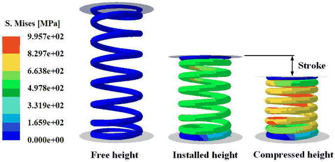
A spring that meets the required force at the required deflection can still fail in the field if the wire stress exceeds the fatigue limit at the inner coil surface, where curvature concentrates shear stress. Catalog springs come in fixed sizes; when your application needs a specific rate, solid height, or endurance life, you design from scratch. In this lesson you will engineer compression, extension, and torsion springs from load specifications using CadQuery helix sweeps, verify each design with the Wahl correction factor for stress concentration and the Goodman diagram for infinite-life fatigue, and export production-ready STEP and STL files. #SpringDesign #StressAnalysis #MechanicalEngineering
By the end of this lesson, you will be able to:
  Spring Types: Load and Geometry  ──────────────────────────────────────────  COMPRESSION          EXTENSION            TORSION  (resists push)       (resists pull)       (resists twist)
     ↓ F                  ↑ F                   ↻ M   ┌─────┐            ┌───────┐            ┌───────┐   │  O  │ pitch p     │ hook  │            │ leg   │   │  O  │             │ O O O │            │ O O O │   │  O  │ Na coils    │ O O O │ Na coils   │ O O O │ wound   │  O  │             │ O O O │            │ O O O │ coils   │  O  │             │ hook  │            │  leg  │   └─────┘            └───────┘            └───────┘   Free length Lf      Initial tension Fi   Deflection: angle θ   Rate: k = F/δ       Hook stress critical Rate: kθ = M/θ   Stress: shear       Stress: shear        Stress: bending
Compression springs resist axial compressive loads and are the most common spring type. They are wound with space between coils (pitch) and shorten under load.
Typical applications:
Key design parameters:
Extension springs resist axial tensile loads. They are wound with initial tension (coils touching at zero load) and hooks or loops at each end for attachment.
Typical applications:
Key design parameters:
Torsion springs resist rotational loads (torque). The wire is loaded in bending, not shear, which fundamentally changes the stress analysis.
Typical applications:
Key design parameters:
The fundamental equations for a close-coiled helical compression spring with round wire:
The spring rate (stiffness) relates force to deflection:
where:
The spring index
Practical range:
Free length for a compression spring with squared-and-ground ends:
where:
where
Music Wire (ASTM A228)
Tensile strength: 1600-2200 MPa (varies with diameter) Max temp: 120 C (250 F) Shear modulus: G = 81,700 MPa Use: High-quality springs, instruments, general purpose. The most common spring wire material.
Stainless Steel 302 (ASTM A313)
Tensile strength: 1200-1800 MPa Max temp: 260 C (500 F) Shear modulus: G = 69,000 MPa Use: Corrosive environments, food processing, medical devices. Lower strength than music wire but excellent corrosion resistance.
Chrome Vanadium (ASTM A231)
Tensile strength: 1400-1900 MPa Max temp: 220 C (430 F) Shear modulus: G = 77,200 MPa Use: Automotive valve springs, high-fatigue applications. Excellent fatigue resistance and impact properties.
Chrome Silicon (ASTM A401)
Tensile strength: 1500-2000 MPa Max temp: 245 C (475 F) Shear modulus: G = 77,200 MPa Use: High-stress, high-temperature applications. Superior to chrome vanadium for shock loading.
Spring wire is manufactured in standard diameters. Always select the nearest standard size:
# Standard music wire diameters (mm) — partial tableMUSIC_WIRE_DIAMETERS = [    0.10, 0.12, 0.14, 0.16, 0.18, 0.20, 0.22, 0.25,    0.28, 0.30, 0.35, 0.40, 0.45, 0.50, 0.55, 0.60,    0.65, 0.70, 0.80, 0.90, 1.00, 1.10, 1.20, 1.40,    1.60, 1.80, 2.00, 2.20, 2.50, 2.80, 3.00, 3.50,    4.00, 4.50, 5.00, 5.50, 6.00, 6.50, 7.00, 8.00,    9.00, 10.00, 11.00, 12.00, 13.00, 14.00, 15.00, 16.00,]
# Approximate tensile strength of music wire (Sut in MPa)# Using the empirical formula: Sut = A / d^m# For music wire (ASTM A228): A = 2211 MPa·mm^m, m = 0.145def music_wire_tensile_strength(d_mm: float) -> float:    """Approximate ultimate tensile strength of music wire.
    Based on curve fit to ASTM A228 data.    Args:        d_mm: Wire diameter in mm    Returns:        Ultimate tensile strength in MPa    """    A = 2211.0  # MPa·mm^m    m = 0.145    return A / (d_mm ** m)
def select_wire_diameter(d_required: float) -> float: """Select the nearest standard wire diameter >= required.""" for d_std in MUSIC_WIRE_DIAMETERS: if d_std >= d_required: return d_std raise ValueError( f"Required diameter {d_required} mm exceeds " f"maximum standard size {MUSIC_WIRE_DIAMETERS[-1]} mm" )The simple torsional shear stress formula
The Wahl correction factor
The corrected maximum shear stress at the inner surface of the coil is:
For design safety, this stress must not exceed the allowable shear stress:
where
import numpy as np
def wahl_factor(C: float) -> float:    """Compute the Wahl correction factor.
    Args:        C: Spring index (D/d), must be >= 3
    Returns:        Wahl factor K_w    """    if C < 3:        raise ValueError(f"Spring index C={C} is too low (min 3)")    return (4*C - 1) / (4*C - 4) + 0.615 / C
def max_shear_stress(F: float, D: float, d: float) -> float:    """Compute maximum shear stress with Wahl correction.
    Args:        F: Applied force (N)        D: Mean coil diameter (mm)        d: Wire diameter (mm)
    Returns:        Maximum shear stress (MPa)    """    C = D / d    Kw = wahl_factor(C)    tau = Kw * 8 * F * D / (np.pi * d**3)    return tau
# Example: 50 N force, 20mm mean coil diameter, 2mm wiretau = max_shear_stress(F=50, D=20, d=2.0)print(f"Wahl factor: {wahl_factor(20/2):.3f}")print(f"Max shear stress: {tau:.1f} MPa")Springs in cyclic applications (valve springs, suspension springs) must be designed for infinite life, typically
For a spring cycling between a minimum force
where the alternating and mean forces are:
The Goodman line defines the boundary between safe (infinite life) and unsafe (finite life) operation:
where:
def goodman_fatigue_check(    F_min: float, F_max: float,    D: float, d: float,    S_ut: float,    shot_peened: bool = False,    n_f_required: float = 1.5) -> dict:    """Perform Goodman fatigue analysis on a helical spring.
    Args:        F_min: Minimum cyclic force (N)        F_max: Maximum cyclic force (N)        D: Mean coil diameter (mm)        d: Wire diameter (mm)        S_ut: Ultimate tensile strength of wire (MPa)        shot_peened: Whether the spring is shot-peened        n_f_required: Required fatigue safety factor
    Returns:        Dictionary with stress values and safety factor    """    C = D / d    Kw = wahl_factor(C)
    # Alternating and mean forces    F_a = (F_max - F_min) / 2    F_m = (F_max + F_min) / 2
    # Corrected alternating and mean shear stresses    tau_a = Kw * 8 * F_a * D / (np.pi * d**3)    tau_m = Kw * 8 * F_m * D / (np.pi * d**3)
    # Material properties    S_su = 0.67 * S_ut    # Ultimate shear strength    if shot_peened:        S_se = 0.40 * S_ut  # Endurance limit (peened)    else:        S_se = 0.30 * S_ut  # Endurance limit (unpeened)
    # Goodman safety factor    # tau_a/S_se + tau_m/S_su = 1/n_f    # Solving for n_f:    goodman_sum = tau_a / S_se + tau_m / S_su    if goodman_sum > 0:        n_f = 1.0 / goodman_sum    else:        n_f = float('inf')
    return {        'F_a': F_a,        'F_m': F_m,        'tau_a_MPa': tau_a,        'tau_m_MPa': tau_m,        'S_se_MPa': S_se,        'S_su_MPa': S_su,        'Kw': Kw,        'C': C,        'n_f': n_f,        'infinite_life': n_f >= n_f_required,    }
# Example: spring cycling between 20N and 80Nresult = goodman_fatigue_check(    F_min=20, F_max=80,    D=18, d=2.0,    S_ut=music_wire_tensile_strength(2.0),    shot_peened=False,    n_f_required=1.5)
for key, val in result.items(): if isinstance(val, float): print(f" {key}: {val:.3f}") else: print(f" {key}: {val}")import matplotlib.pyplot as pltimport numpy as np
def plot_goodman_diagram(result: dict, title: str = "Goodman Diagram"): """Plot the Goodman diagram showing the operating point relative to the failure boundary.
Args: result: Output from goodman_fatigue_check() """ S_se = result['S_se_MPa'] S_su = result['S_su_MPa'] tau_a = result['tau_a_MPa'] tau_m = result['tau_m_MPa']
fig, ax = plt.subplots(1, 1, figsize=(8, 6))
# Goodman line (failure boundary) tau_m_line = np.linspace(0, S_su, 100) tau_a_line = S_se * (1 - tau_m_line / S_su) ax.plot(tau_m_line, tau_a_line, 'r-', linewidth=2, label='Goodman line (failure)')
# Yield line: tau_a + tau_m = S_sy S_sy = 0.45 * (S_se / 0.30) # Back-calculate S_ut tau_a_yield = np.linspace(0, S_sy, 100) tau_m_yield = S_sy - tau_a_yield ax.plot(tau_m_yield, tau_a_yield, 'b--', linewidth=1.5, label='Yield line')
# Safe region (shaded) ax.fill_between(tau_m_line, 0, tau_a_line, alpha=0.1, color='green', label='Safe region')
# Operating point ax.plot(tau_m, tau_a, 'ko', markersize=10, zorder=5) ax.annotate( f'Operating point\n' f'n_f = {result["n_f"]:.2f}', xy=(tau_m, tau_a), xytext=(tau_m + S_su*0.05, tau_a + S_se*0.1), fontsize=10, arrowprops=dict(arrowstyle='->', color='black'), bbox=dict(boxstyle='round,pad=0.3', facecolor='yellow', alpha=0.8), )
# Load line from origin through operating point if tau_m > 0: slope = tau_a / tau_m tau_m_load = np.linspace(0, S_su, 100) tau_a_load = slope * tau_m_load mask = tau_a_load <= S_se * 1.1 ax.plot(tau_m_load[mask], tau_a_load[mask], 'g:', linewidth=1, label='Load line')
ax.set_xlabel('Mean Shear Stress τ_m (MPa)', fontsize=12) ax.set_ylabel('Alternating Shear Stress τ_a (MPa)', fontsize=12) ax.set_title(title, fontsize=14) ax.legend(loc='upper right') ax.set_xlim(0, S_su * 1.1) ax.set_ylim(0, S_se * 1.1) ax.grid(True, alpha=0.3)
plt.tight_layout() plt.savefig("goodman_diagram.png", dpi=150) plt.show()
# Plot for our example# plot_goodman_diagram(result, "Spring Fatigue — Goodman Diagram")import cadquery as cqimport numpy as np
def compression_spring( d: float, # Wire diameter (mm) D: float, # Mean coil diameter (mm) N_a: float, # Number of active coils L_f: float, # Free length (mm) end_type: str = "squared_ground") -> cq.Workplane: """Generate a 3D compression spring using helix + sweep.
Args: d: Wire diameter (mm) D: Mean coil diameter (mm) N_a: Number of active coils L_f: Free length (mm) end_type: "squared_ground" or "plain"
Returns: CadQuery solid of the spring """ R = D / 2 # Mean coil radius
# Calculate pitch for active coils if end_type == "squared_ground": # Squared-and-ground ends: 1 dead coil each end active_length = L_f - 2 * d pitch = active_length / N_a total_coils = N_a + 2 else: pitch = L_f / N_a total_coils = N_a
# Generate helix as a series of points points_per_coil = 72 # Angular resolution total_points = int(total_coils * points_per_coil)
helix_points = [] for i in range(total_points + 1): t = i / points_per_coil # t in coil numbers
angle = 2 * np.pi * (i / points_per_coil)
# Axial position with end transitions if end_type == "squared_ground": if t < 1.0: # First dead coil: transition from zero pitch z = d * (t / 1.0) # Linear ramp to pitch elif t > total_coils - 1.0: # Last dead coil: transition back to zero pitch t_end = t - (total_coils - 1.0) z_start = d + (N_a) * pitch z = z_start + d * (1.0 - t_end / 1.0) else: # Active coils: constant pitch z = d + (t - 1.0) * pitch else: z = t * pitch
x = R * np.cos(angle) y = R * np.sin(angle) helix_points.append((x, y, z))
# Create helix path as a spline path = cq.Workplane("XY").spline(helix_points)
# Create wire cross-section at the start of the helix # Position the circle at the first point, normal to the helix wire_profile = ( cq.Workplane("YZ") .transformed(offset=(R, 0, helix_points[0][2])) .circle(d / 2) )
# Sweep the circular profile along the helix path spring = wire_profile.sweep(path, isFrenet=True)
return spring
# Design a compression springspring = compression_spring( d=2.0, # 2mm wire diameter D=16.0, # 16mm mean coil diameter N_a=8, # 8 active coils L_f=45.0, # 45mm free length end_type="squared_ground")
# Exportcq.exporters.export(spring, "compression_spring.step")cq.exporters.export(spring, "compression_spring.stl")import cadquery as cqimport numpy as np
def extension_spring( d: float, # Wire diameter (mm) D: float, # Mean coil diameter (mm) N_a: float, # Number of active coils (body) hook_length: float = None, # Hook straight length (mm)) -> cq.Workplane: """Generate a 3D extension spring with hooks.
Extension springs have zero pitch in the body (coils touch) and hooks at each end.
Args: d: Wire diameter (mm) D: Mean coil diameter (mm) N_a: Number of active body coils hook_length: Length of straight hook section (mm). Defaults to D (one coil diameter).
Returns: CadQuery solid of the spring """ R = D / 2 if hook_length is None: hook_length = D
# Body: tightly wound coils (pitch = wire diameter) body_pitch = d # Coils touching body_length = N_a * body_pitch
points_per_coil = 72 total_body_points = int(N_a * points_per_coil)
# Build full path: bottom hook + body + top hook all_points = []
# Bottom hook: half-loop + straight section hook_points = 36 # Half a coil for i in range(hook_points + 1): angle = np.pi * (i / hook_points) # 0 to pi # Hook curves from center out to coil radius hx = R * np.sin(angle) hy = -R * np.cos(angle) # Start pointing down hz = -hook_length * (1 - i / hook_points) all_points.append((hx, hy, hz))
# Body coils for i in range(total_body_points + 1): angle = np.pi + 2 * np.pi * (i / points_per_coil) t = i / points_per_coil x = R * np.cos(angle) y = R * np.sin(angle) z = t * body_pitch all_points.append((x, y, z))
# Top hook: half-loop + straight section z_top = body_length start_angle = np.pi + 2 * np.pi * N_a for i in range(1, hook_points + 1): angle = start_angle + np.pi * (i / hook_points) hx = R * np.cos(angle) hy = R * np.sin(angle) hz = z_top + hook_length * (i / hook_points) all_points.append((hx, hy, hz))
# Create path and sweep path = cq.Workplane("XY").spline(all_points)
wire_profile = ( cq.Workplane("YZ") .transformed(offset=( all_points[0][0], all_points[0][1], all_points[0][2] )) .circle(d / 2) )
spring = wire_profile.sweep(path, isFrenet=True) return spring
# Extension spring: 1.5mm wire, 12mm coil, 15 coilsext_spring = extension_spring( d=1.5, D=12.0, N_a=15, hook_length=14.0)cq.exporters.export(ext_spring, "extension_spring.step")import cadquery as cqimport numpy as np
def torsion_spring( d: float, # Wire diameter (mm) D: float, # Mean coil diameter (mm) N_a: float, # Number of active coils leg_length: float, # Length of straight legs (mm) leg_angle: float = 90.0, # Angle between legs (degrees)) -> cq.Workplane: """Generate a 3D torsion spring with straight legs.
Torsion springs have zero pitch (coils touching) with two straight legs that extend tangentially.
Args: d: Wire diameter (mm) D: Mean coil diameter (mm) N_a: Number of body coils leg_length: Length of each straight leg (mm) leg_angle: Angle between the two legs (degrees)
Returns: CadQuery solid of the spring """ R = D / 2 body_pitch = d # Coils touching
points_per_coil = 72 total_body_points = int(N_a * points_per_coil)
all_points = []
# First leg: straight section tangent to the coil # Extends tangentially from the start of the coil n_leg_pts = 20 start_angle = 0 # Tangent direction at start: perpendicular to radius tx = -np.sin(start_angle) ty = np.cos(start_angle) for i in range(n_leg_pts, 0, -1): frac = i / n_leg_pts lx = R * np.cos(start_angle) + tx * leg_length * frac ly = R * np.sin(start_angle) + ty * leg_length * frac lz = 0 all_points.append((lx, ly, lz))
# Body coils for i in range(total_body_points + 1): angle = start_angle + 2 * np.pi * (i / points_per_coil) t = i / points_per_coil x = R * np.cos(angle) y = R * np.sin(angle) z = t * body_pitch all_points.append((x, y, z))
# Second leg: extends tangentially at the end end_angle = start_angle + 2 * np.pi * N_a # Adjust for desired angle between legs leg2_angle = end_angle tx2 = -np.sin(leg2_angle) ty2 = np.cos(leg2_angle) z_end = N_a * body_pitch for i in range(1, n_leg_pts + 1): frac = i / n_leg_pts lx = R * np.cos(leg2_angle) + tx2 * leg_length * frac ly = R * np.sin(leg2_angle) + ty2 * leg_length * frac lz = z_end all_points.append((lx, ly, lz))
# Create path and sweep path = cq.Workplane("XY").spline(all_points)
wire_profile = ( cq.Workplane("YZ") .transformed(offset=( all_points[0][0], all_points[0][1], all_points[0][2] )) .circle(d / 2) )
spring = wire_profile.sweep(path, isFrenet=True) return spring
# Torsion spring: 1.2mm wire, 10mm coil, 5 coils, 25mm legstorsion = torsion_spring( d=1.2, D=10.0, N_a=5, leg_length=25.0, leg_angle=90.0)cq.exporters.export(torsion, "torsion_spring.step")This section walks through the full design process from a load specification to a verified, exportable spring.
| Parameter | Value |
|---|---|
| Maximum load | 80 N |
| Minimum load | 20 N |
| Working deflection | 15 mm |
| Maximum outer diameter | 22 mm |
| Material | Music wire (ASTM A228) |
| Life requirement | Infinite life ( |
| End type | Squared and ground |
Determine spring rate from load and deflection requirements
Select wire diameter and compute coil geometry
Verify static stress with Wahl correction
Verify fatigue life with Goodman analysis
Compute all physical dimensions and generate 3D model
import numpy as np
# === DESIGN REQUIREMENTS ===F_max = 80.0     # N, maximum working loadF_min = 20.0     # N, minimum load (installed)delta_w = 15.0   # mm, working deflection (F_max - F_min)OD_max = 22.0    # mm, maximum outer diametermaterial = "music_wire"G = 81_700.0     # MPa, shear modulus (music wire)n_s = 1.3        # Static safety factorn_f = 1.5        # Fatigue safety factor
# === STEP 1: Spring Rate ===k = (F_max - F_min) / delta_w  # N/mmprint(f"Required spring rate: k = {k:.2f} N/mm")
# === STEP 2: Wire Diameter and Coil Geometry ===# Start with a trial spring index C = 8 (good starting point)C_trial = 8.0
# Iterate: select wire diameter, compute coil geometry# The design equation for wire diameter from stress limit:# d >= (8 * K_w * F_max * C / (pi * tau_allow))^(1/3)
# Trial wire diametersfor d_trial in [1.6, 1.8, 2.0, 2.2, 2.5]:    D = C_trial * d_trial    OD = D + d_trial
    if OD > OD_max:        continue
    # Number of active coils    N_a = G * d_trial**4 / (8 * D**3 * k)
    if N_a < 3 or N_a > 20:        continue
    # Free length (squared-and-ground ends)    # Solid height    L_s = (N_a + 2) * d_trial    # Deflection at F_max    delta_max = F_max / k    # Clash allowance (15% of working deflection)    delta_clash = 0.15 * delta_w    L_f = L_s + delta_max + delta_clash
    # Check stress    Kw = wahl_factor(C_trial)    tau_max = Kw * 8 * F_max * D / (np.pi * d_trial**3)    S_ut = music_wire_tensile_strength(d_trial)    S_sy = 0.45 * S_ut    tau_allow = S_sy / n_s
    # Check fatigue    fatigue = goodman_fatigue_check(        F_min, F_max, D, d_trial, S_ut,        shot_peened=False, n_f_required=n_f    )
    print(f"\n--- Trial: d = {d_trial} mm ---")    print(f"  D = {D:.1f} mm, OD = {OD:.1f} mm")    print(f"  N_a = {N_a:.1f} coils")    print(f"  L_f = {L_f:.1f} mm, L_s = {L_s:.1f} mm")    print(f"  tau_max = {tau_max:.1f} MPa")    print(f"  tau_allow = {tau_allow:.1f} MPa")    print(f"  Static OK: {tau_max < tau_allow}")    print(f"  S_ut = {S_ut:.0f} MPa")    print(f"  Fatigue n_f = {fatigue['n_f']:.2f}")    print(f"  Infinite life: {fatigue['infinite_life']}")
# === STEP 3: Select Best Design ===# Choose d = 2.0 mm based on results aboved = 2.0                          # mm (standard music wire)D = C_trial * d                  # 16.0 mm mean coil diameterOD = D + d                       # 18.0 mm outer diameterID = D - d                       # 14.0 mm inner diameterN_a = G * d**4 / (8 * D**3 * k)  # Active coilsN_a = round(N_a)                 # Round to nearest integer
# Recalculate actual spring rate with rounded N_ak_actual = G * d**4 / (8 * D**3 * N_a)print(f"\n=== FINAL DESIGN ===")print(f"Wire diameter:     d = {d} mm")print(f"Mean coil diameter: D = {D} mm")print(f"Outer diameter:    OD = {OD} mm")print(f"Inner diameter:    ID = {ID} mm")print(f"Active coils:      N_a = {N_a}")print(f"Spring rate:       k = {k_actual:.3f} N/mm")
# Physical dimensionsL_s = (N_a + 2) * ddelta_max = F_max / k_actualdelta_clash = 0.15 * (F_max - F_min) / k_actualL_f = L_s + delta_max + delta_clashpitch = (L_f - 2 * d) / N_a
print(f"Solid height:      L_s = {L_s:.1f} mm")print(f"Free length:       L_f = {L_f:.1f} mm")print(f"Pitch:             p = {pitch:.2f} mm")print(f"Total coils:       N_t = {N_a + 2}")
# === STEP 4: Final Verification ===Kw = wahl_factor(D / d)tau_max = Kw * 8 * F_max * D / (np.pi * d**3)S_ut = music_wire_tensile_strength(d)S_sy = 0.45 * S_utn_static = S_sy / tau_max
fatigue_final = goodman_fatigue_check(    F_min, F_max, D, d, S_ut,    shot_peened=False, n_f_required=n_f)
print(f"\n=== STRESS VERIFICATION ===")print(f"Wahl factor: K_w = {Kw:.3f}")print(f"Max shear stress: tau = {tau_max:.1f} MPa")print(f"Shear yield: S_sy = {S_sy:.0f} MPa")print(f"Static safety: n_s = {n_static:.2f}")print(f"Fatigue safety: n_f = {fatigue_final['n_f']:.2f}")print(f"Infinite life: {fatigue_final['infinite_life']}")# === STEP 5: Generate 3D Geometry ===spring_3d = compression_spring( d=d, D=D, N_a=N_a, L_f=L_f, end_type="squared_ground")
# Export production filescq.exporters.export(spring_3d, "spring_verified.step")cq.exporters.export(spring_3d, "spring_verified.stl")
print("\nExported: spring_verified.step, spring_verified.stl")Buckling Prevention
Springs with a free-length-to-diameter ratio
Surge Frequency
The natural frequency of a compression spring must be at least 13x higher than the operating frequency to avoid resonance (surge). Natural frequency:
Set Removal
New springs are typically compressed to solid height during manufacturing (“set removal” or “presetting”). This induces beneficial residual stresses and raises the apparent yield strength by approximately 10-15%. Always specify set-removed springs for fatigue applications.
End Conditions
Squared-and-ground ends provide the best perpendicularity and load distribution. Plain ends are cheaper but create eccentric loading. For critical applications, specify squareness tolerance (typically 3 degrees maximum).
Extension springs have a unique characteristic, initial tension
The initial tension is created during winding by twisting the wire as it is coiled. Typical initial tension ranges:
The recommended range for
def extension_spring_design(    F_max: float,       # Maximum load (N)    F_i: float,         # Initial tension (N)    delta_max: float,   # Maximum deflection (mm)    D: float,           # Mean coil diameter (mm)    d: float,           # Wire diameter (mm)    G: float = 81_700,  # Shear modulus (MPa)) -> dict:    """Design an extension spring with initial tension.
    Returns dictionary of design parameters.    """    # Spring rate (not counting initial tension)    k = (F_max - F_i) / delta_max
    # Active coils    N_a = G * d**4 / (8 * D**3 * k)
    # Body length (coils touching)    L_body = (N_a + 1) * d  # +1 for end coil
    # Hook stress concentration factor (typical)    # Hooks have higher stress than the body    K_hook = (4 * (D/d)**2 - (D/d) - 1) / (4 * (D/d) * ((D/d) - 1))
    # Maximum body stress    C = D / d    Kw = wahl_factor(C)    tau_body = Kw * 8 * F_max * D / (np.pi * d**3)
    # Hook bending stress (the critical point)    sigma_hook = K_hook * 16 * F_max * D / (np.pi * d**3)
    return {        'k_N_per_mm': k,        'N_a': N_a,        'L_body_mm': L_body,        'tau_body_MPa': tau_body,        'sigma_hook_MPa': sigma_hook,        'K_hook': K_hook,    }
Torsion springs are loaded in bending, not shear. The maximum bending stress on the inner surface of the coil is:
where
The angular rate of a torsion spring is:
where
Design from Requirements
Start with force, deflection, and space constraints. Derive wire diameter, coil geometry, and coil count from the spring rate equation. Select the nearest standard wire gauge.
Always Check Stress
The Wahl correction factor accounts for curvature-induced stress concentration. Ignoring it underestimates the true maximum shear stress by 15-30% for typical spring indices.
Fatigue is Non-Negotiable
For any spring that cycles, perform a Goodman analysis. Shot-peening the spring increases the endurance limit by approximately 33% and is standard practice for fatigue-critical springs.
Code = Repeatable Design
The complete design calculation, verification, and 3D generation pipeline runs in seconds. Change one requirement and the entire design updates, including stress checks and geometry.
Next lesson: In the capstone project, we close the loop between CadQuery geometry generation and FreeCAD FEM analysis. You will build a parametric bracket, automatically mesh and solve with CalculiX, sweep a 3D parameter space, and select the optimal design from a Pareto front.
Comments