Skip to content

Thermal Modeling for Electronics

Thermal Modeling for Electronics hero image
Modified:
Published:

Every electronic component generates heat, and every component has a maximum temperature it can tolerate. The gap between those two facts is where thermal design lives. In this lesson you will build thermal resistance networks in Python, simulate transient heat-up, and create a heatsink sizer tool that gives you a clear answer: safe or danger. The same math that models RC circuits (Lesson 2) works perfectly for heat flow. #ThermalModeling #HeatsinkDesign #Electronics

What We Are Building

Heatsink Sizer Tool

A Python tool that models the thermal path from silicon junction to ambient air. You input: component power dissipation, thermal resistances (junction-to-case, case-to-heatsink, heatsink-to-ambient), thermal capacitances, and ambient temperature. The tool outputs: steady-state junction temperature, time to reach 90% of steady state, and a clear “SAFE” or “DANGER” verdict based on the component’s maximum rated temperature.

Project specifications:

ParameterValue
Thermal ModelLumped-parameter resistance-capacitance network
NodesJunction, Case, Heatsink, Ambient
SolverSciPy solve_ivp for transient response
Steady-StateAnalytical (sum of thermal resistances times power)
OutputTemperature vs. time for each node, steady-state summary, safety verdict

Thermal-Electrical Analogy


Heat flow follows the same math as electrical current flow. This analogy lets you reuse everything you learned about RC circuits.

Thermal DomainElectrical DomainSymbol
Temperature (C)Voltage (V) /
Heat flow (W)Current (A) /
Thermal resistance (C/W)Electrical resistance (ohm) /
Thermal capacitance (J/C)Electrical capacitance (F) /

Just as voltage drops across resistors in series, temperature drops across thermal resistances in series:

where is power dissipation, is junction-to-case, is case-to-sink, and is sink-to-ambient.

The Thermal Network


Power In (P)
|
v
+--------+
|Junction| T_j Thermal capacitance: C_j
+---+----+
|
R_jc Junction-to-Case resistance
|
+---+----+
| Case | T_c Thermal capacitance: C_c
+---+----+
|
R_cs Case-to-Sink resistance (thermal paste/pad)
|
+---+----+
|Heatsink| T_s Thermal capacitance: C_s
+---+----+
|
R_sa Sink-to-Ambient resistance (convection)
|
+---+----+
|Ambient | T_a Fixed (room temperature)
+--------+

Governing Equations

For each node, the energy balance gives a first-order ODE:

Junction node:

Case node:

Heatsink node:

The ambient temperature is fixed (it acts as the “ground” in the electrical analogy). The exponential solution to these first-order ODEs comes from the same calculus used in Newton’s law of cooling. For that foundation, see Applied Mathematics: Calculus for Engineers.

Complete Python Code


Save this as heatsink_sizer.py:

"""
Heatsink Sizer Tool
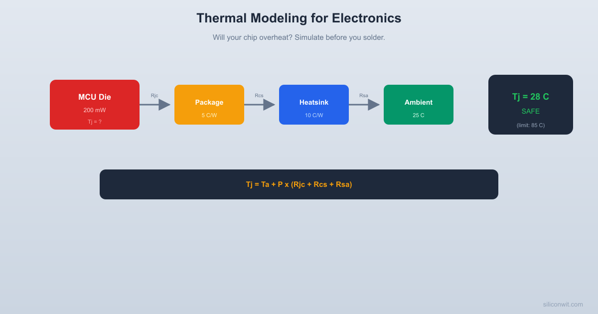
Models the thermal path from silicon junction to ambient.
Simulates transient heat-up and gives a SAFE/DANGER verdict.
"""
import numpy as np
from scipy.integrate import solve_ivp
import matplotlib.pyplot as plt
# -------------------------------------------------------
# Component database (example entries)
# -------------------------------------------------------
COMPONENTS = {
"STM32F4 (LQFP-64)": {
"power_w": 0.200,
"t_max_c": 85.0,
"r_jc": 30.0, # C/W, junction-to-case
"c_j": 0.5, # J/C, junction thermal capacitance
"c_c": 2.0, # J/C, case thermal capacitance
},
"LM7805 Regulator": {
"power_w": 2.5,
"t_max_c": 125.0,
"r_jc": 5.0,
"c_j": 1.0,
"c_c": 3.0,
},
"Power MOSFET (TO-220)": {
"power_w": 5.0,
"t_max_c": 150.0,
"r_jc": 1.5,
"c_j": 0.8,
"c_c": 5.0,
},
}
# -------------------------------------------------------
# Heatsink options
# -------------------------------------------------------
HEATSINKS = {
"None (bare component)": {
"r_cs": 0.0, # No interface
"r_sa": 200.0, # Very high (natural convection from case only)
"c_s": 0.0,
},
"Small clip-on (25x25 mm)": {
"r_cs": 1.0, # Thermal pad/paste
"r_sa": 20.0, # Modest fin area
"c_s": 10.0, # Aluminum mass
},
"Medium extruded (50x50 mm)": {
"r_cs": 0.5,
"r_sa": 8.0,
"c_s": 30.0,
},
"Large finned (100x100 mm)": {
"r_cs": 0.5,
"r_sa": 3.0,
"c_s": 80.0,
},
"Fan-cooled (50x50 mm + fan)": {
"r_cs": 0.5,
"r_sa": 2.0,
"c_s": 30.0,
},
}
def thermal_ode(t, y, P, R_jc, R_cs, R_sa, C_j, C_c, C_s, T_a):
"""
Thermal network ODE.
y = [T_junction, T_case, T_heatsink]
"""
T_j, T_c, T_s = y
# Handle degenerate case: no heatsink (C_s = 0)
# In that case, T_s tracks T_c closely
if C_s < 0.01:
# No separate heatsink node; collapse case and heatsink
# Use R_jc for junction-to-case, then R_sa from case to ambient
dTj_dt = (P - (T_j - T_c) / R_jc) / C_j
dTc_dt = ((T_j - T_c) / R_jc - (T_c - T_a) / R_sa) / C_c
dTs_dt = 0.0 # Unused
else:
dTj_dt = (P - (T_j - T_c) / R_jc) / C_j
dTc_dt = ((T_j - T_c) / R_jc - (T_c - T_s) / R_cs) / C_c
dTs_dt = ((T_c - T_s) / R_cs - (T_s - T_a) / R_sa) / C_s
return [dTj_dt, dTc_dt, dTs_dt]
def steady_state_temp(P, R_jc, R_cs, R_sa, T_a):
"""Calculate steady-state junction temperature analytically."""
R_total = R_jc + R_cs + R_sa
T_j_ss = T_a + P * R_total
T_c_ss = T_a + P * (R_cs + R_sa)
T_s_ss = T_a + P * R_sa
return T_j_ss, T_c_ss, T_s_ss, R_total
def analyze_thermal(component_name, heatsink_name, T_ambient=25.0,
t_end=None, plot=True):
"""
Run full thermal analysis for a component + heatsink combination.
Returns steady-state junction temperature and safety verdict.
"""
comp = COMPONENTS[component_name]
sink = HEATSINKS[heatsink_name]
P = comp["power_w"]
R_jc = comp["r_jc"]
R_cs = sink["r_cs"]
R_sa = sink["r_sa"]
C_j = comp["c_j"]
C_c = comp["c_c"]
C_s = sink["c_s"]
T_max = comp["t_max_c"]
# Steady state
T_j_ss, T_c_ss, T_s_ss, R_total = steady_state_temp(
P, R_jc, R_cs, R_sa, T_ambient)
is_safe = T_j_ss <= T_max
margin = T_max - T_j_ss
# Estimate time constant for simulation duration
# Dominant time constant is roughly (C_j + C_c + C_s) * R_total
C_total = C_j + C_c + max(C_s, 0.01)
tau_est = C_total * R_total
if t_end is None:
t_end = max(5 * tau_est, 60.0)
# Simulate transient
sol = solve_ivp(
lambda t, y: thermal_ode(t, y, P, R_jc, R_cs, R_sa,
C_j, C_c, C_s, T_ambient),
[0, t_end],
[T_ambient, T_ambient, T_ambient], # Start at ambient
dense_output=True,
max_step=t_end / 500
)
t = np.linspace(0, t_end, 1000)
y = sol.sol(t)
T_j_t = y[0]
T_c_t = y[1]
T_s_t = y[2]
# Find time to reach 90% of steady-state rise
delta_T = T_j_ss - T_ambient
target_90 = T_ambient + 0.9 * delta_T
idx_90 = np.where(T_j_t >= target_90)[0]
t_90 = t[idx_90[0]] if len(idx_90) > 0 else t_end
# Print results
print("=" * 55)
print(" THERMAL ANALYSIS")
print("=" * 55)
print(f" Component: {component_name}")
print(f" Heatsink: {heatsink_name}")
print(f" Power: {P*1000:.0f} mW")
print(f" Ambient temp: {T_ambient:.0f} C")
print("-" * 55)
print(f" R_jc: {R_jc:.1f} C/W")
print(f" R_cs: {R_cs:.1f} C/W")
print(f" R_sa: {R_sa:.1f} C/W")
print(f" R_total: {R_total:.1f} C/W")
print("-" * 55)
print(f" Junction temp: {T_j_ss:.1f} C (steady-state)")
print(f" Case temp: {T_c_ss:.1f} C (steady-state)")
print(f" Heatsink temp: {T_s_ss:.1f} C (steady-state)")
print(f" Max rated: {T_max:.0f} C")
print(f" Margin: {margin:.1f} C")
print(f" Time to 90%: {t_90:.1f} seconds")
print("-" * 55)
if is_safe:
print(f" Verdict: SAFE ({margin:.1f} C margin)")
else:
print(f" Verdict: DANGER (exceeds max by "
f"{abs(margin):.1f} C)")
print("=" * 55)
result = {
"T_j_ss": T_j_ss, "T_c_ss": T_c_ss, "T_s_ss": T_s_ss,
"is_safe": is_safe, "margin": margin, "t_90": t_90,
"t": t, "T_j_t": T_j_t, "T_c_t": T_c_t, "T_s_t": T_s_t,
}
return result
def compare_heatsinks(component_name, T_ambient=25.0):
"""
Compare all heatsink options for a given component.
"""
print(f"\n{'='*55}")
print(f" HEATSINK COMPARISON: {component_name}")
print(f"{'='*55}\n")
comp = COMPONENTS[component_name]
T_max = comp["t_max_c"]
fig, axes = plt.subplots(1, 2, figsize=(14, 5))
fig.suptitle(f"Thermal Analysis: {component_name} ({comp['power_w']*1000:.0f} mW)",
fontsize=13, fontweight="bold")
colors = ["tab:red", "tab:orange", "tab:blue", "tab:green", "tab:purple"]
summary_data = []
for idx, (sink_name, sink) in enumerate(HEATSINKS.items()):
result = analyze_thermal(component_name, sink_name,
T_ambient, plot=False)
color = colors[idx % len(colors)]
# Transient plot
axes[0].plot(result["t"], result["T_j_t"], color=color,
linewidth=2, label=sink_name)
summary_data.append({
"name": sink_name,
"T_j_ss": result["T_j_ss"],
"safe": result["is_safe"],
"margin": result["margin"],
"t_90": result["t_90"],
})
# Format transient plot
axes[0].axhline(y=T_max, color="red", linestyle="--", linewidth=2,
alpha=0.7, label=f"Max rated ({T_max:.0f} C)")
axes[0].axhline(y=T_ambient, color="gray", linestyle=":", alpha=0.3)
axes[0].set_xlabel("Time (seconds)")
axes[0].set_ylabel("Junction Temperature (C)")
axes[0].set_title("Transient Temperature Rise")
axes[0].legend(fontsize=7, loc="lower right")
axes[0].grid(True, alpha=0.3)
# Bar chart of steady-state temperatures
names = [d["name"] for d in summary_data]
temps = [d["T_j_ss"] for d in summary_data]
bar_colors = ["tab:red" if not d["safe"] else "tab:green"
for d in summary_data]
y_pos = np.arange(len(names))
axes[1].barh(y_pos, temps, color=bar_colors, alpha=0.7, height=0.6)
axes[1].axvline(x=T_max, color="red", linestyle="--", linewidth=2,
alpha=0.7, label=f"Max ({T_max:.0f} C)")
axes[1].set_yticks(y_pos)
axes[1].set_yticklabels(names, fontsize=8)
axes[1].set_xlabel("Steady-State Junction Temp (C)")
axes[1].set_title("Heatsink Comparison")
axes[1].legend(fontsize=8)
axes[1].grid(True, alpha=0.3, axis="x")
# Add temperature labels on bars
for i, temp in enumerate(temps):
axes[1].text(temp + 1, i, f"{temp:.0f} C", va="center", fontsize=8)
plt.tight_layout()
filename = component_name.split("(")[0].strip().lower().replace(" ", "_")
plt.savefig(f"thermal_{filename}.png", dpi=150, bbox_inches="tight")
plt.show()
print(f"\nSaved: thermal_{filename}.png\n")
# -------------------------------------------------------
# Practical example: STM32 thermal design
# -------------------------------------------------------
def stm32_example():
"""
Detailed example: Will an STM32F4 at 200 mW survive without a heatsink?
"""
print("\n" + "=" * 55)
print(" PRACTICAL EXAMPLE: STM32F4 THERMAL DESIGN")
print("=" * 55)
# Without heatsink
print("\n--- Without heatsink ---")
r1 = analyze_thermal("STM32F4 (LQFP-64)", "None (bare component)",
T_ambient=25.0, plot=False)
# With small heatsink
print("\n--- With small clip-on heatsink ---")
r2 = analyze_thermal("STM32F4 (LQFP-64)", "Small clip-on (25x25 mm)",
T_ambient=25.0, plot=False)
print("\n" + "-" * 55)
print(" SUMMARY")
print("-" * 55)
print(f" Without heatsink: {r1['T_j_ss']:.1f} C", end="")
if not r1["is_safe"]:
print(f" ** EXCEEDS {85} C LIMIT **")
else:
print(f" (margin: {r1['margin']:.1f} C)")
print(f" With heatsink: {r2['T_j_ss']:.1f} C", end="")
if not r2["is_safe"]:
print(f" ** EXCEEDS {85} C LIMIT **")
else:
print(f" (margin: {r2['margin']:.1f} C)")
print("-" * 55)
# Plot both transients
fig, ax = plt.subplots(figsize=(10, 5))
ax.plot(r1["t"], r1["T_j_t"], "tab:red", linewidth=2,
label="No heatsink")
ax.plot(r2["t"], r2["T_j_t"], "tab:blue", linewidth=2,
label="Small clip-on heatsink")
ax.axhline(y=85, color="red", linestyle="--", linewidth=2,
alpha=0.6, label="Max rated (85 C)")
ax.axhline(y=25, color="gray", linestyle=":", alpha=0.3,
label="Ambient (25 C)")
ax.set_xlabel("Time (seconds)")
ax.set_ylabel("Junction Temperature (C)")
ax.set_title("STM32F4 at 200 mW: Heatsink vs. No Heatsink",
fontweight="bold")
ax.legend(fontsize=9)
ax.grid(True, alpha=0.3)
plt.tight_layout()
plt.savefig("stm32_thermal.png", dpi=150, bbox_inches="tight")
plt.show()
print("\nSaved: stm32_thermal.png")
# -------------------------------------------------------
# Main
# -------------------------------------------------------
if __name__ == "__main__":
# Run the STM32 practical example first
stm32_example()
# Compare all heatsink options for the power MOSFET
compare_heatsinks("Power MOSFET (TO-220)")
# Compare for the voltage regulator
compare_heatsinks("LM7805 Regulator")

Running the Heatsink Sizer


Terminal window
python heatsink_sizer.py

The first thing it prints is the STM32 example:

=======================================================
PRACTICAL EXAMPLE: STM32F4 THERMAL DESIGN
=======================================================
--- Without heatsink ---
=======================================================
THERMAL ANALYSIS
=======================================================
Component: STM32F4 (LQFP-64)
Heatsink: None (bare component)
Power: 200 mW
Ambient temp: 25 C
-------------------------------------------------------
R_jc: 30.0 C/W
R_cs: 0.0 C/W
R_sa: 200.0 C/W
R_total: 230.0 C/W
-------------------------------------------------------
Junction temp: 71.0 C (steady-state)
Max rated: 85 C
Margin: 14.0 C
Verdict: SAFE (14.0 C margin)
=======================================================

Your STM32 at 200 mW reaches 71 C without a heatsink, which is within the 85 C limit but with only 14 C of margin. In a hot enclosure (40 C ambient), it would reach 86 C and exceed the limit. Adding a small clip-on heatsink drops it to 35 C with a comfortable 50 C margin.

Practical Thermal Design Rules


Every component datasheet lists thermal resistances:

  • : junction-to-case (fixed by the package, you cannot change it)
  • : junction-to-ambient (measured on a standard PCB with no heatsink, useful as a worst-case reference)

To use the model in this lesson, you need from the datasheet and from the heatsink datasheet. The case-to-sink resistance depends on the thermal interface material (typically 0.2 to 2.0 C/W for thermal paste, 1 to 5 C/W for a thermal pad).

When Steady-State Is Not Enough


The transient simulation matters when:

  1. Pulsed loads: A power amplifier that transmits for 10 ms every second may never reach the steady-state temperature. The peak junction temperature depends on the thermal capacitance, not just the resistance.

  2. Startup sequences: During boot, a microcontroller might draw 3x its normal current for a few seconds. The simulation shows the temperature spike.

  3. Thermal cycling: Repeated heating and cooling causes mechanical stress (solder joint fatigue). The simulation shows the temperature swing, which drives reliability calculations.

Experiments to Try


Pulsed Power

Modify the power input to be pulsed: 5 W for 100 ms, then 0 W for 900 ms (10% duty cycle, 0.5 W average). Compare the peak junction temperature to the steady-state at 0.5 W continuous. Thermal capacitance makes a big difference here.

Hot Ambient

Rerun the STM32 example at 40 C, 50 C, and 60 C ambient. At what ambient temperature does it exceed the 85 C limit without a heatsink?

Custom Component

Add your own component to the COMPONENTS dictionary. Use the thermal resistance values from its datasheet and see which heatsink you need.

Forced Convection

Adding a fan reduces dramatically. Modify the heatsink database to include various fan speeds and see the effect on junction temperature.

Key Takeaways


  1. Thermal networks are RC circuits

    The same math applies. Temperature is voltage, heat flow is current, thermal resistance is electrical resistance, and thermal mass is capacitance. If you can simulate an RC circuit, you can simulate a heatsink.

  2. Steady-state temperature is just Ohm’s law

    . This one equation answers most thermal design questions.

  3. Transient response depends on thermal mass

    A large heatsink takes longer to heat up. This is good for pulsed loads (the peak temperature is lower) but bad for startup (you wait longer before the system reaches operating temperature).

  4. Always check at worst-case ambient

    A design that works at 25 C ambient may fail at 50 C. The simulation makes it trivial to sweep ambient temperature and find the threshold.

  5. Datasheets give you the numbers you need

    comes from the component datasheet. comes from the heatsink datasheet. comes from the thermal interface material datasheet. Plug them in and simulate.

Next Lesson


In the final lesson, we bring everything together with control system design. You will model a DC motor, design a PID controller, tune the gains in simulation, and analyze the closed-loop response. When the simulation looks right, you paste the gains into firmware.

Control System Design in Simulation →


Comments

Loading comments...
© 2021-2026 SiliconWit®. All rights reserved.