Timers are the workhorses of embedded systems. They count clock cycles in hardware, freeing the CPU to do other work while generating precise time intervals, PWM signals, and frequency outputs. The ATmega328P has three timers, and in this lesson you will configure all of them. The project is a tone generator: two buttons step the frequency up and down, and a piezo buzzer plays the tone using Timer1 in CTC mode with hardware output compare. You will hear exactly how prescalers and compare values translate into audible frequencies. #Timers #CTC #PWM
What We Are Building
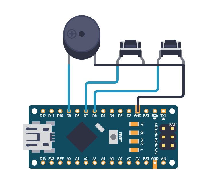
Tunable Tone Generator
A piezo buzzer driven by Timer1 in CTC mode with hardware toggle on the OC1A pin. Two push buttons adjust the frequency up and down in semitone steps across two octaves (C4 through C6, roughly 262 Hz to 1047 Hz). The frequency calculation is done entirely from the timer formula: f = F_CPU / (2 * prescaler * (1 + OCR1A)). No delay loops are involved in tone generation.
Project specifications:
Parameter
Value
MCU
ATmega328P (on Arduino Nano or Uno)
Timer
Timer1 (16-bit) in CTC mode
Output pin
OC1A (PB1, Arduino D9)
Frequency range
262 Hz to 1047 Hz
Steps
Semitone increments (12 per octave)
Prescaler
8 (gives good resolution in audible range)
Buttons
Up (PD6), Down (PD7)
Parts for This Lesson
Ref
Component
Quantity
Notes
1
Arduino Nano or Uno (ATmega328P)
1
From previous lessons
2
Breadboard
1
From previous lessons
3
Piezo buzzer (passive)
1
Must be passive, not active
4
Push buttons (tactile)
2
Reuse 1 from Lesson 2, add 1 new
5
Jumper wires
~8
Male-to-male
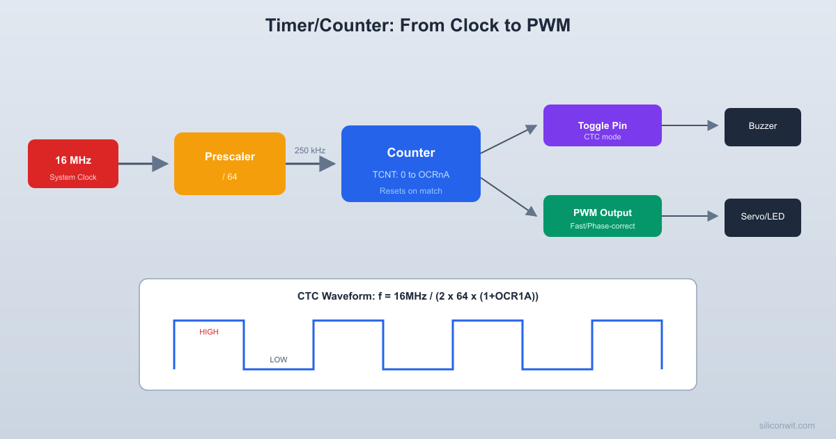
Timer Architecture Overview
The timer subsystem takes the system clock, divides it through a prescaler, and feeds the result into a counter register. When the counter reaches a compare value or overflows, it can trigger actions like toggling an output pin or firing an interrupt.
Each timer in the ATmega328P is a hardware counter clocked by the system clock (or a prescaled version of it). Timer0 and Timer2 are 8-bit (count 0 to 255), while Timer1 is 16-bit (count 0 to 65535). The timer increments on each clock tick and can trigger actions when it reaches specific values.
Timer
Width
Compare Channels
PWM Pins
Special Features
Timer0
8-bit
OCR0A, OCR0B
OC0A (PD6), OC0B (PD5)
Used by Arduino delay()
Timer1
16-bit
OCR1A, OCR1B
OC1A (PB1), OC1B (PB2)
Input capture, 16-bit resolution
Timer2
8-bit
OCR2A, OCR2B
OC2A (PB3), OC2B (PD3)
Async mode with external 32 kHz crystal
Timer Modes
Mode
How It Works
Use Case
Normal
Counts 0 to MAX, overflows to 0
Simple timing, overflow interrupts
CTC (Clear Timer on Compare)
Counts 0 to OCRnA, resets to 0
Precise frequency generation
Fast PWM
Counts 0 to MAX (or OCRnA), single slope
LED dimming, motor speed
Phase Correct PWM
Counts up then down, dual slope
Smoother analog output
Prescaler Options
The prescaler divides the system clock before it reaches the timer counter. A 16 MHz clock with prescaler 8 gives a 2 MHz timer tick, meaning each count takes 0.5 microseconds. Larger prescalers allow longer intervals but reduce resolution. For a broader look at how counters, prescalers, and frequency dividers work at the digital logic level, see Digital Electronics: Counters, Timers, and Dividers.
Prescaler
Timer Clock (at 16 MHz)
Tick Period
8-bit Max Period
16-bit Max Period
1
16 MHz
62.5 ns
16 us
4.1 ms
8
2 MHz
500 ns
128 us
32.8 ms
64
250 kHz
4 us
1.024 ms
262 ms
256
62.5 kHz
16 us
4.096 ms
1.049 s
1024
15.625 kHz
64 us
16.384 ms
4.194 s
CTC Mode Frequency Formula
In CTC mode, the timer counts from 0 to the value in OCRnA, then resets. If you configure the output compare pin to toggle on each match, you get a square wave.
  CTC mode waveform (toggle on compare match):
  TCNTn    ^    |     /|    /|    /|    /|  OCRnA /  |  /  |  /  |  /  |    | /    |/    |/    |/    |    +------+-----+-----+------> time           reset reset reset
  OC1A pin (toggle mode):    ____      ____      ____   |    |    |    |    |    |   |    |____|    |____|    |___         ^         ^      one period = 2*(1+OCRnA) ticks
The frequency of that square wave is:
f_out = F_CPU / (2 * prescaler * (1 + OCR1A))
Solving for OCR1A:
OCR1A = (F_CPU / (2 * prescaler * f_out)) - 1
For example, to generate 440 Hz (concert A) with prescaler 8:
OCR1A = (16000000 / (2 * 8 * 440)) - 1 = 2272
Semitone Frequency Table
Musical notes follow an exponential scale where each semitone is the previous frequency multiplied by the twelfth root of 2 (approximately 1.0595). The table below gives OCR1A values for two octaves starting from Middle C, calculated with prescaler 8.
Note
Frequency (Hz)
OCR1A (prescaler 8)
C4
262
3816
C#4
277
3607
D4
294
3400
D#4
311
3213
E4
330
3029
F4
349
2862
F#4
370
2702
G4
392
2550
G#4
415
2406
A4
440
2272
A#4
466
2144
B4
494
2023
C5
523
1910
C6
1047
954
Complete Firmware
#defineF_CPU16000000UL
#include<avr/io.h>
#include<util/delay.h>
/* OCR1A values for C4 to C6 (25 semitones, prescaler 8) */
while (!(PIND & (1<< BTN_UP))); /* Wait for release */
_delay_ms(50);
}
if (debounce(BTN_DOWN)) {
if (note_idx >0) {
note_idx--;
OCR1A =notes[note_idx];
}
while (!(PIND & (1<< BTN_DOWN)));
_delay_ms(50);
}
}
}
How the Hardware Toggle Works
Setting COM1A0 in TCCR1A tells the hardware to toggle the OC1A pin every time TCNT1 matches OCR1A. The timer automatically resets to 0 (CTC mode), and the cycle repeats. This produces a square wave with a period of 2 * (1 + OCR1A) timer ticks. The CPU does not need to execute any code for the tone to keep playing; it only intervenes when you change the frequency.
PWM Mode Preview
CTC mode generates precise frequencies, but timers can also produce variable-width pulses. PWM (Pulse Width Modulation) is a technique where you rapidly switch a digital pin on and off at a fixed frequency, varying the fraction of time it stays on (the “duty cycle”) to control the average power delivered to a load. Fast PWM mode uses the same counter and compare registers, but instead of toggling the pin at each match, it controls how long the pin stays high within each cycle. You will use this extensively in later lessons for motor control and LED dimming.
  Fast PWM waveform:
  TCNTn    ^ MAX|    /|    /|    /|    |   / |   / |   / | OCR|--/--+--/--+--/--+-- duty cycle    | /   | /   | /   |    |/    |/    |/    |    +-----+-----+-----+-----> time
  Output pin:    ___   ___   ___   |   | |   | |   |   |   |_|   |_|   |_______    <-->    duty = OCRnA / MAX
The duty cycle controls the average voltage. You will use PWM extensively in later lessons for analog-like outputs.
/* Example: Fast PWM on Timer0, ~62.5 kHz, 50% duty */
Add a third button that mutes the tone by disconnecting the output compare (clear COM1A0 in TCCR1A) and re-enables it on the next press.
Program a melody: store a sequence of note indices and durations in an array, then play them in order using Timer1 for the tone and a delay loop for timing.
Use Timer0 in Normal mode with an overflow interrupt to create a 1 ms system tick. Use this tick to implement a non-blocking button debouncer.
Calculate the exact frequency error for each note in the semitone table. How far off is each note from the ideal frequency, and which notes have the largest error?
Summary
You now understand how the ATmega328P timers work at the register level. You can configure CTC mode for precise frequency generation, calculate OCR values from a target frequency, and use hardware output compare to generate signals without CPU intervention. The prescaler and compare value together determine the output frequency with a simple formula. These concepts carry directly into PWM, input capture, and interrupt-driven timing in the lessons ahead.
Comments