Scissor lifts appear in car jacks, warehouse platforms, aerial work platforms, laboratory jacks, and loading dock levelers. Despite the simple appearance (two crossed arms and an actuator), the force analysis is far from trivial: actuator force approaches infinity near collapse, stability degrades with height, and the choice of actuator type and joint configuration changes everything. This simulator provides complete analysis across all these dimensions. #ScissorLift #MechanismSimulator #ForceAnalysis
Full kinematic profiles across the operating angle range. Platform height follows h = nL sin(theta), but velocity and acceleration reveal non-obvious behavior: the platform decelerates as it rises even with constant actuator speed.
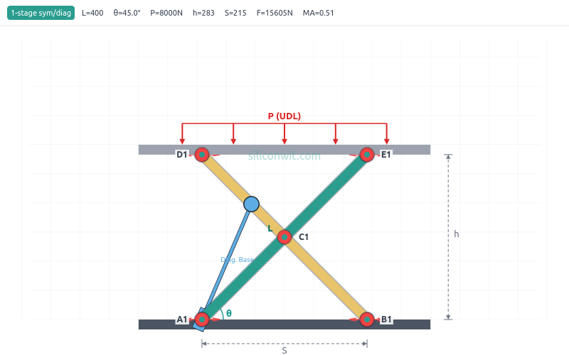
Force and Mechanical Advantage
Actuator force varies as 1/tan(theta), creating a hyperbolic spike near collapse. Compare actual mechanical advantage (including link weight) against ideal MA. Critical for hydraulic cylinder and motor sizing.
Joint Pin Forces and Link Stress
Center pin and base pin resultant forces across the full range. Per-side force breakdown for eccentric loads. Bending stress estimates for structural design of the scissor arms.
Energy, Power, and Stability
Potential energy accumulation, power requirements, and stability analysis with tipping angle and safety factor. Essential for hydraulic power unit selection and safe operating envelope design.
Key Features
Real-Time Animation
Watch the scissor lift rise and fall with properly rendered rounded-bar arms, pin-hole joints, base and top platforms, and load arrows. All elements scale proportionally across presets from tiny lab jacks to large aerial platforms.
Twelve Analysis Plots in Four Groups
Kinematics (height, velocity, acceleration, actuator length, base spread), Force Analysis (actuator force, mechanical advantage with ideal MA overlay, joint pin forces, link stress), Energy (potential energy and cumulative work), and Stability (tipping angle and safety factor on dual axes).
A/B Configuration Comparison
Save one configuration as Experiment A, change any parameter, and run Experiment B. Both datasets overlay on every chart with distinct colors and line styles.
UDL and Point Load Support
Default is uniform distributed load (UDL), representing pallets, equipment, or people spread across the platform. Switch to point load with configurable offset to analyze eccentric loading, tipping risk, and per-side force imbalance.
Two Configurations, Three Actuator Types
Symmetric (both pivots slide) or left-pinned (one pivot fixed). Horizontal-base hydraulic, horizontal-center lead screw, or diagonal cylinder. Six combinations, each with different force, stroke, and efficiency characteristics.
Eight Real-World Presets
Warehouse Lift, Car Jack, Aerial Platform, Lab Jack, Loading Dock, Auto Hoist, Electric Table, and Work Table. Each configures link length, stages, load, mass, actuator type, and joint arrangement for a specific application.
Professional Downloads
Export PNG charts, design specifications with manufacturing tolerances, lab report templates, and full kinematic/force datasets.
Preset Configurations
The simulator includes eight engineering presets representing real applications:
Preset
L (mm)
Stages
Load (N)
Config
Actuator
Warehouse Lift
700
3
2000
Symmetric
Horizontal Base
Car Jack
300
1
5000
Left-Pinned
Horizontal Base
Aerial Platform
1200
3
3000
Symmetric
Horizontal Base
Lab Jack
80
1
50
Symmetric
Lead Screw
Loading Dock
400
1
8000
Symmetric
Horizontal Base
Auto Hoist
500
2
10000
Left-Pinned
Diagonal
Electric Table
350
1
1500
Left-Pinned
Lead Screw
Work Table
450
1
3000
Symmetric
Diagonal
Each preset configures all parameters to values representative of the application: actuator type, joint configuration, operating angle range, link mass, and actuator speed.
Equations
The simulator implements exact analytical solutions for all configurations:
Height per stage:
h = n * L * sin(theta)
Actuator force (symmetric, horizontal-base):
F = W_eff / (2 * tan(theta))
where W_eff = P + (total link weight) / 2
Actuator force (left-pinned, horizontal-base):
F = W_eff / tan(theta)
Diagonal actuator length:
D = L * sqrt(0.09 * cos^2(theta) + 0.49 * sin^2(theta))
Comments