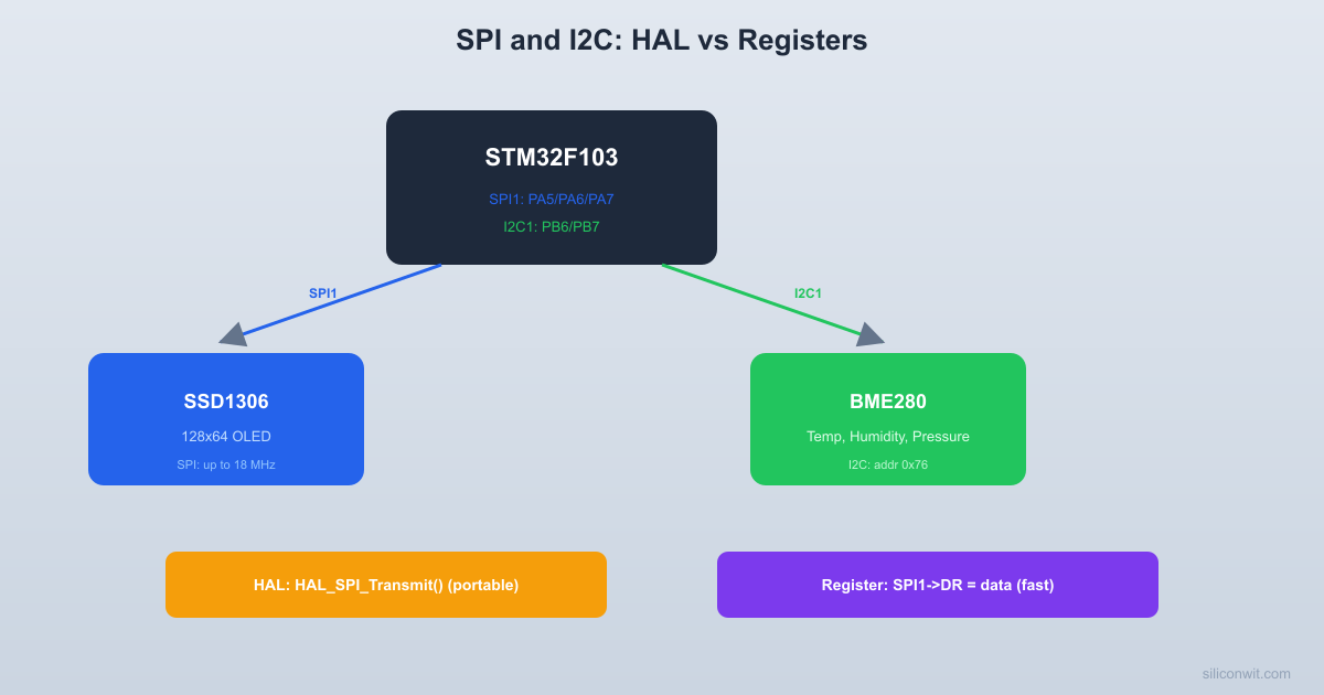
Every STM32 project eventually needs to communicate with external chips over SPI or I2C, and every developer faces the same question: use ST’s HAL library or write register-level code? In this lesson you will answer that question with data. You will wire up an SSD1306 OLED display (SPI) and a BME280 environmental sensor (I2C), write both drivers at the register level and with HAL, then measure the differences in flash usage, RAM footprint, and transaction speed. #STM32 #SPI #I2C
What We Are Building
Sensor Dashboard on OLED Display
A real-time dashboard showing temperature, humidity, and pressure readings from a BME280 sensor on a 128x64 SSD1306 OLED display. The OLED is connected over SPI for fast screen updates, and the BME280 communicates over I2C. Both drivers exist in HAL and register-level versions so you can switch between them at compile time and compare the results.
The STM32F103 has two SPI peripherals: SPI1 on the APB2 bus (72 MHz max) and SPI2 on APB1 (36 MHz max).
  SPI1 wiring to SSD1306 OLED:
  Blue Pill              SSD1306 OLED  +----------+           +----------+  |          |           |          |  | PA5 SCK -+---------->| D0 CLK   |  | PA7 MOSI-+---------->| D1 MOSI  |  | PA4 CS  -+---------->| CS       |  | PA3 DC  -+---------->| DC       |  | PA2 RST -+---------->| RES      |  |          |           |          |  | 3.3V ----+---------->| VCC      |  | GND -----+---------->| GND      |  +----------+           +----------+
  DC pin: LOW = command, HIGH = data  CS pin: LOW = selected (active)
SPI1 can run at up to 18 MHz in master mode (72 MHz / 4), which is plenty fast for driving OLED displays. SPI is a synchronous, full-duplex protocol with four signals: SCK (clock), MOSI (master out, slave in), MISO (master in, slave out), and CS (chip select, active low).
The SSD1306 is a common OLED controller with a 128x64 pixel monochrome display. In SPI mode it uses a DC (data/command) pin to distinguish between commands (DC low) and display data (DC high). The initialization sequence configures the display timing, contrast, memory addressing mode, and turns the display on. After initialization, you write pixel data as a 1024-byte framebuffer (128 columns x 8 pages, each page is 8 pixels tall).
The I2C1 peripheral connects to the BME280 sensor. Both SDA and SCL are open-drain with external pull-ups provided by the BME280 breakout board.
  I2C1 wiring to BME280:
  Blue Pill              BME280  +----------+           +----------+  |          |     VCC   |          |  |          |      |    |          |  |          |    [4.7K] |          |  |          |      |    |          |  | PB6 SCL -+------+-->| SCL      |  |          |           |          |  |          |     VCC   |          |  |          |      |    |          |  |          |    [4.7K] |          |  |          |      |    |          |  | PB7 SDA -+------+-<>| SDA      |  |          |           |          |  | GND -----+--------->| GND SDO  |  | 3.3V ----+--------->| VCC CSB  |  +----------+           +----------+
  SDO to GND: address = 0x76  SDO to VCC: address = 0x77
The STM32F103 I2C peripheral is notoriously tricky at the register level. It has known silicon errata (especially around the BUSY flag getting stuck) and requires careful sequencing of register reads and writes. This is one area where HAL genuinely saves debugging time. We will implement both approaches so you can see the complexity difference firsthand.
I2C Pin Configuration
I2C pins must be configured as alternate function open-drain. The STM32’s internal pull-ups are too weak for I2C; the BME280 module typically includes 4.7k pull-up resistors on board.
*temp_c100 = (cal.t_fine*5+128) >>8; /* Celsius x 100 */
/* Pressure and humidity compensation follow similar formulas */
/* (full implementation from Bosch reference code) */
(void)adc_P;
(void)adc_H;
*press_pa =101325; /* Placeholder */
*hum_q10 =500; /* Placeholder */
}
HAL vs Register Level: The Comparison
The project uses both SPI and I2C buses simultaneously, each talking to a different peripheral. The STM32 CPU orchestrates both without conflicts because they are independent hardware blocks.
  Dual-bus architecture:
            STM32F103  +---------------------------+  |                           |  |  SPI1 (18 MHz)            |  |    PA5 SCK  ----+         |  |    PA7 MOSI ----+--> SSD1306  |    PA4 CS   ----+    OLED  |    PA3 DC   ----+   (display)  |                           |  |  I2C1 (400 kHz)           |  |    PB6 SCL  ----+         |  |    PB7 SDA  ----+--> BME280  |                  |   (sensor)  +---------------------------+
After building both versions, here is what we measured on a real Blue Pill:
Metric
Register Level
HAL
Flash usage (full project)
~4.2 KB
~12.8 KB
RAM usage
~1.2 KB
~1.8 KB
SPI byte transfer time
~0.5 us
~1.2 us
I2C single register read
~28 us
~45 us
I2C burst read (8 bytes)
~85 us
~120 us
Lines of driver code
~180
~40
Debug difficulty
Higher (must know registers)
Lower (descriptive API)
When to Use Which
Use register-level code when flash space is critical (bootloaders, tiny chips), when you need maximum speed (bit-banging, real-time control), or when you want deep understanding of the peripheral. Use HAL when development speed matters more than binary size, when your team needs readable and portable code, or when you are prototyping and may switch STM32 families later. Many professional projects use a mix: HAL for complex peripherals (USB, Ethernet) and register access for simple, performance-critical paths (GPIO toggling, tight timer loops).
Comments