Servos expect a very specific PWM signal: a pulse every 20 ms, with the pulse width encoding the target angle. Getting this right requires precise timer configuration, and the STM32 timer subsystem is one of the most capable (and complex) peripherals on the chip. In this lesson you will generate servo-grade PWM, read an encoder using the timer’s built-in hardware encoder mode, and combine both into a smooth pan mechanism that tracks your finger on the knob. #STM32 #Timers #PWM
What We Are Building
Servo Pan Mechanism with Encoder Control
A servo motor that pans left and right based on rotary encoder input. The encoder is read using TIM3’s hardware encoder interface (no software polling needed), and the servo is driven by TIM2’s PWM output. Rotating the encoder clockwise pans the servo right; counterclockwise pans it left. The position is displayed on the serial terminal along with the raw encoder count and servo pulse width.
Project specifications:
Parameter
Value
Board
Blue Pill (STM32F103C8T6)
Servo
SG90 micro servo (or compatible)
Servo PWM pin
PA0 (TIM2_CH1)
PWM period
20 ms (50 Hz)
Pulse width range
0.5 ms (0 degrees) to 2.5 ms (180 degrees)
Encoder timer
TIM3 in encoder mode
Encoder pins
PA6 (TIM3_CH1), PA7 (TIM3_CH2)
Encoder button
PB5 (GPIO input, center/reset position)
Serial output
USART1 on PA9 (115200 baud)
Bill of Materials
Component
Quantity
Notes
Blue Pill (STM32F103C8T6)
1
From previous lessons
ST-Link V2 clone
1
From previous lessons
SG90 micro servo
1
4.8-6V operating voltage
KY-040 rotary encoder
1
From Lesson 2
Breadboard + jumper wires
1 set
From previous lessons
External 5V supply (optional)
1
For servo power if USB is insufficient
STM32 Timer Overview
The STM32F103 has seven timers, each with different capabilities. Understanding which timer to use for which task is essential for efficient peripheral allocation. All timers share a common counting core but differ in channel count, resolution, and special features.
Timer
Type
Channels
Resolution
Special Features
TIM1
Advanced
4
16-bit
Complementary outputs, dead-time, break input
TIM2
General-purpose
4
16-bit
Encoder mode, PWM, input capture
TIM3
General-purpose
4
16-bit
Encoder mode, PWM, input capture
TIM4
General-purpose
4
16-bit
Encoder mode, PWM, input capture
TIM5
General-purpose
4
16-bit
(Not on all F103 variants)
TIM6
Basic
0
16-bit
DAC trigger, timebase only
TIM7
Basic
0
16-bit
DAC trigger, timebase only
Timer Clock Source
TIM2, TIM3, and TIM4 are on the APB1 bus, which runs at 36 MHz. However, when the APB1 prescaler is greater than 1 (which it is, since we divide by 2 to get 36 MHz from 72 MHz), the timer clock is automatically doubled to 72 MHz. This means all general-purpose timers run at 72 MHz despite being on the 36 MHz APB1 bus. TIM1, being on APB2, also runs at 72 MHz directly.
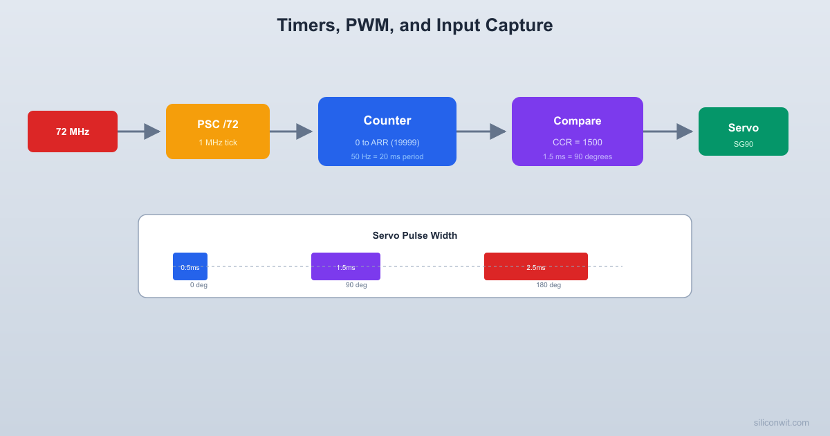
A standard hobby servo expects a PWM signal with a 20 ms period (50 Hz). The pulse width within that period determines the shaft angle.
  Servo PWM signal:
  |<----------- 20 ms (50 Hz) ---------->|
  0 deg:     ___                           ___            |   |                         |   |  __________| 0.5ms |_____________________| 0.5ms            |<->|
  90 deg:    ______                        ___            |      |                      |  __________| 1.5ms  |___________________| 1.5            |<---->|
  180 deg:   _________                     ___            |         |                   |  __________| 2.5ms     |________________| 2.5            |<------->|
The pulse width within that period controls the angle: 0.5 ms for 0 degrees, 1.5 ms for 90 degrees (center), and 2.5 ms for 180 degrees. Some servos accept a slightly wider range, but these values are safe for nearly all servos including the SG90.
PWM Configuration
voidservo_pwm_init(void) {
/* Enable clocks for GPIOA and TIM2 */
RCC->APB2ENR|= RCC_APB2ENR_IOPAEN;
RCC->APB1ENR|= RCC_APB1ENR_TIM2EN;
/* PA0 as alternate function push-pull, 50 MHz */
GPIOA->CRL&=~(0xF<<0);
GPIOA->CRL|= (0xB<<0);
/*
* Timer clock = 72 MHz
* PSC = 72 - 1 = 71 -> counter clock = 1 MHz (1 us per tick)
* ARR = 20000 - 1 -> period = 20 ms (50 Hz)
*
* CCR1 = 500 -> 0.5 ms pulse -> 0 degrees
* CCR1 = 1500 -> 1.5 ms pulse -> 90 degrees
* CCR1 = 2500 -> 2.5 ms pulse -> 180 degrees
*/
TIM2->PSC=72-1;
TIM2->ARR=20000-1;
TIM2->CCR1=1500; /* Start at center (90 degrees) */
The STM32 timers support several output compare modes beyond basic PWM:
Mode
OC1M bits
Behavior
Frozen
000
Output unaffected by comparison
Active on match
001
Set output high on match
Inactive on match
010
Set output low on match
Toggle
011
Toggle output on match
Force low
100
Force output low
Force high
101
Force output high
PWM mode 1
110
High when counter < CCR, low otherwise
PWM mode 2
111
Low when counter < CCR, high otherwise
Hardware Encoder Interface (TIM3)
In Lesson 2 we read the encoder in software by polling GPIO pins. The STM32 timers offer a much better approach: encoder mode. The timer hardware counts directly from the quadrature signals without CPU intervention.
  Hardware encoder mode (TIM3):
  PA6 (TIM3_CH1) ----> TI1 input  PA7 (TIM3_CH2) ----> TI2 input
  +--------+     +---------------+  |Encoder |     |     TIM3      |  | CLK ---+---->| TI1  Encoder  |  | DT  ---+---->| TI2  logic    |  +--------+     |       |       |                 |   +---+---+   |                 |   | CNT   |   |                 |   | (auto |   |                 |   | inc/  |   |                 |   | dec)  |   |                 |   +-------+   |                 +---------------+
  CPU reads TIM3->CNT for position.  Zero CPU overhead during counting.
In this mode, the timer counter automatically increments or decrements based on the quadrature signals, with no CPU intervention needed. You simply read the timer’s CNT register to get the current position. This eliminates missed steps during heavy CPU load and is the standard approach in motor control applications.
Encoder Mode Configuration
voidencoder_hw_init(void) {
/* Enable clocks for GPIOA and TIM3 */
RCC->APB2ENR|= RCC_APB2ENR_IOPAEN;
RCC->APB1ENR|= RCC_APB1ENR_TIM3EN;
/* PA6 (TIM3_CH1) and PA7 (TIM3_CH2) as input floating */
GPIOA->CRL&=~((0xF<<24) | (0xF<<28));
GPIOA->CRL|= ((0x4<<24) | (0x4<<28));
/*
* Encoder mode 3: count on both TI1 and TI2 edges
* This gives 4x resolution (4 counts per detent on KY-040)
/* Input filter: 4 samples at fDTS/2 (debouncing) */
TIM3->CCMR1|= (0x3<<4) | (0x3<<12);
/* Set auto-reload to maximum for free-running counter */
TIM3->ARR=0xFFFF;
/* Start at midpoint so we can detect both directions */
TIM3->CNT=32768;
/* Enable the timer */
TIM3->CR1|= TIM_CR1_CEN;
}
int16_tencoder_hw_read(void) {
return (int16_t)(TIM3->CNT-32768);
}
Encoder Mode Comparison
Approach
Pros
Cons
Software polling (Lesson 2)
Simple, any GPIO pin
Misses steps under load, uses CPU
Hardware encoder mode
Zero CPU usage, never misses steps
Requires specific timer pins
External interrupt (EXTI)
Works on any EXTI pin
Interrupt overhead, possible missed edges
Input Capture
Input capture records the timer counter value at the moment an external signal edge occurs. By comparing two successive captures, you get the signal period.
  Input capture for period measurement:
  Signal: _____       _________       ____               |     |         |     |               |_____|         |_____|                ^                ^           capture1          capture2           (CNT=1000)        (CNT=6000)
  Period = capture2 - capture1         = 6000 - 1000 = 5000 ticks  At 1 MHz timer clock: 5000 us = 5 ms  Frequency = 1 / 0.005 = 200 Hz
This is useful for measuring pulse widths, signal frequencies, and time intervals between events. While we do not use input capture in the servo project, understanding it completes the timer peripheral picture and prepares you for sensor interfacing in later lessons.
Comments