Serial communication is how your microcontroller talks to the outside world. In this lesson you will configure the ATmega328P USART peripheral from scratch, calculating baud rates from register values, setting frame formats, and implementing both blocking and interrupt-driven transmit/receive. The project is a temperature logger: an NTC thermistor feeds the ADC, the firmware converts the reading to degrees Celsius using the Steinhart-Hart equation, and streams timestamped CSV lines over UART for capture and plotting on a PC. #UART #Serial #DataLogging
What We Are Building
Temperature Logger with CSV Export
A continuous temperature logger that samples an NTC thermistor once per second, converts the ADC reading to Celsius, and transmits CSV-formatted data (timestamp, raw ADC, temperature) over UART at 9600 baud. On the PC side, you capture the serial stream to a file and plot it with Python, a spreadsheet, or any tool that reads CSV. A ring buffer handles transmit buffering so the main loop never blocks on UART.
Project specifications:
Parameter
Value
MCU
ATmega328P (on Arduino Nano or Uno)
USART
USART0, 9600 baud, 8N1
Sensor
10K NTC thermistor (B=3950)
ADC channel
ADC0 (PC0, Arduino A0)
Sample rate
1 Hz
Output format
CSV: timestamp_ms, adc_raw, temp_c
TX buffer
64-byte ring buffer
Parts for This Lesson
Ref
Component
Quantity
Notes
1
Arduino Nano or Uno (ATmega328P)
1
From previous lessons
2
Breadboard
1
From previous lessons
3
10K NTC thermistor
1
Glass bead or epoxy type
4
10K ohm resistor
1
Voltage divider partner
5
Jumper wires
~4
Male-to-male
USART Register Overview
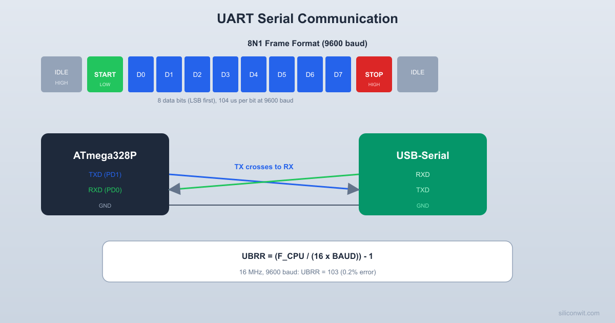
A UART frame at 8N1 consists of a start bit (always low), eight data bits (LSB first), and a stop bit (always high). The idle state is high, so the receiver detects the falling edge of the start bit to begin sampling each bit at the center of its period.
  UART 8N1 frame format (one byte):
  Idle  Start D0  D1  D2  D3  D4  D5  D6  D7 Stop Idle  ____       ___     ___         ___ ___ ___  _______      |     |   |   |   |       |   |   |   |      |_____|   |___|   |_______|   |   |   |       ^                                      ^     start                                  stop     bit                                    bit
  Bit period = 1 / baud_rate  At 9600 baud: ~104 us per bit  Total frame: 10 bits = ~1.04 ms
The ATmega328P has one USART peripheral (USART0) controlled by five registers. UDR0 is the data register for both transmit and receive. UCSR0A holds status flags (transmit complete, receive complete, data register empty). UCSR0B enables the transmitter, receiver, and interrupts. UCSR0C sets the frame format. UBRR0 (split into UBRR0H and UBRR0L) sets the baud rate.
The baud rate is derived from the system clock and the UBRR value. In normal speed mode (U2X0 = 0), the formula is: UBRR = (F_CPU / (16 * BAUD)) - 1. For 16 MHz and 9600 baud: UBRR = (16000000 / (16 * 9600)) - 1 = 103. The actual baud rate with UBRR=103 is 9615, giving an error of 0.16%, which is well within the acceptable range.
Baud Rate
UBRR (16 MHz)
Actual Baud
Error
2400
416
2400
0.0%
9600
103
9615
0.2%
19200
51
19231
0.2%
38400
25
38462
0.2%
57600
16
58824
2.1%
115200
8
111111
3.5%
UART Initialization
#defineF_CPU16000000UL
#defineBAUD9600
#defineUBRR_VAL ((F_CPU / (16UL* BAUD)) -1)
staticvoiduart_init(void)
{
/* Set baud rate */
UBRR0H = (uint8_t)(UBRR_VAL >>8);
UBRR0L = (uint8_t)(UBRR_VAL);
/* Enable transmitter and receiver */
UCSR0B = (1<< TXEN0) | (1<< RXEN0);
/* Frame format: 8 data bits, no parity, 1 stop bit (8N1) */
UCSR0C = (1<< UCSZ01) | (1<< UCSZ00);
}
Blocking Transmit and Receive
staticvoiduart_putc(charc)
{
while (!(UCSR0A & (1<< UDRE0))); /* Wait for empty buffer */
UDR0 = c;
}
staticcharuart_getc(void)
{
while (!(UCSR0A & (1<< RXC0))); /* Wait for data */
return UDR0;
}
staticvoiduart_puts(constchar*s)
{
while (*s) uart_putc(*s++);
}
Ring Buffer for Non-Blocking TX
The complete firmware later in this lesson uses blocking TX for simplicity. The ring buffer technique shown here is a common optimization you can apply when your main loop cannot afford to wait for each byte to finish sending.
A ring buffer (circular buffer) decouples the producer (main code adding characters) from the consumer (UART hardware sending them).
  Ring buffer (64 bytes):
  +---+---+---+---+---+---+---+---+  | A | B | C | D |   |   |   |   |  +---+---+---+---+---+---+---+---+    ^               ^    tail            head    (ISR reads      (main writes     next byte)      next byte)
  After ISR sends 'A' and main writes 'E':
  +---+---+---+---+---+---+---+---+  |   | B | C | D | E |   |   |   |  +---+---+---+---+---+---+---+---+        ^               ^        tail            head
  Wraps around when head or tail  reaches the end of the array.
The main code writes to the buffer and enables the UDRE interrupt. The ISR sends one byte at a time and disables itself when the buffer is empty. This prevents the main loop from stalling while long strings are transmitted.
#defineTX_BUF_SIZE64
staticvolatilechartx_buf[TX_BUF_SIZE];
staticvolatileuint8_t tx_head =0;
staticvolatileuint8_t tx_tail =0;
staticvoidtx_enqueue(charc)
{
uint8_t next = (tx_head +1) % TX_BUF_SIZE;
while (next == tx_tail); /* Wait if buffer full */
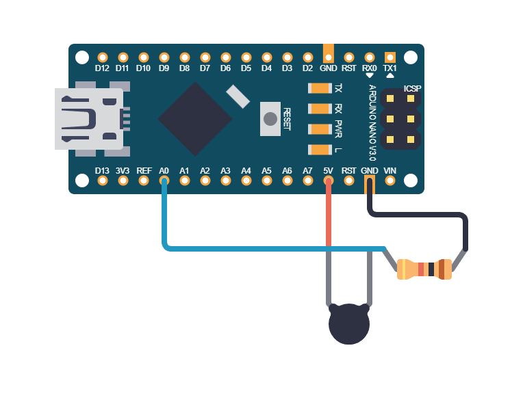
The thermistor and fixed resistor form a voltage divider whose output voltage changes with temperature. The ADC reads this voltage and the firmware converts it to degrees Celsius.
VCC (5V)
|
[NTC] 10K at 25C
| (resistance drops
+--- as temp rises)
|
ADC0 ---+---> to ATmega328P PC0
|
[R1] 10K fixed
|
GND
The NTC thermistor forms a voltage divider with a fixed 10K resistor. The thermistor connects from the ADC input to VCC, and the fixed resistor connects from the ADC input to ground. As temperature increases, the thermistor resistance decreases, and the voltage at the ADC pin drops. The Steinhart-Hart equation (simplified B-parameter version) converts resistance to temperature.
Steinhart-Hart B-Parameter Equation
1/T = 1/T0 + (1/B) * ln(R/R0)
Where T0 = 298.15 K (25 C), R0 = 10000 ohms, and B = 3950 (from the thermistor datasheet).
The voltage at the ADC pin is determined by the voltage divider: V_adc = VCC * R_fixed / (R_therm + R_fixed). Since the 10-bit ADC maps 0 to VCC across 0 to 1023, the ADC reading is adc = 1023 * R_fixed / (R_therm + R_fixed). Solving for R_therm:
Use PuTTY or Tera Term set to 9600 baud, 8N1. Enable session logging to save the CSV output to a file.
import pandas as pd
import matplotlib.pyplot as plt
df = pd.read_csv('temperature_log.csv')
df['time_s'] = df['timestamp_ms'] /1000.0
plt.figure(figsize=(10, 4))
plt.plot(df['time_s'], df['temp_c'])
plt.xlabel('Time (s)')
plt.ylabel('Temperature (C)')
plt.title('NTC Thermistor Log')
plt.grid(True)
plt.tight_layout()
plt.savefig('temperature_plot.png')
plt.show()
Exercises
Implement the ring-buffer based TX from the code earlier in this lesson. Verify that the main loop no longer blocks during UART transmission by toggling an LED and observing that it does not stutter.
Add RX capability: send single-character commands from the PC to change the sample rate. For example, “1” for 1 Hz, “5” for 5 Hz, “0” to pause.
Redirect printf to UART by implementing a custom uart_putchar function and assigning it with fdevopen. Then use printf("%.1f\r\n", temp) instead of manual string formatting.
Calculate and print a running average of the last 10 temperature readings alongside the instantaneous value.
Summary
You now know how to configure the ATmega328P USART from register level: baud rate calculation, frame format, blocking and interrupt-driven I/O, and ring buffers for non-blocking transmission. The temperature logger demonstrates a complete data pipeline from analog sensor through ADC to formatted serial output. UART is the simplest and most universal communication interface in embedded systems, and it will serve as your primary debugging tool in every lesson that follows.
Comments