Every lesson so far has focused on one capability at a time. Now you will combine them all into a real deployment. The capstone is a two-node wireless sensor network: an outdoor node that wakes from deep sleep, reads sensors, publishes over MQTT, and goes back to sleep; and an indoor node that stays powered, subscribes to the same MQTT topics, and displays live readings on an OLED screen. You will handle reconnection, offline buffering, OTA updates for both nodes, and walk through a production readiness checklist. This is what a complete IoT project looks like. #ESP32 #SensorNetwork #Capstone
What We Are Building
Two-Node Connected Sensor Network
A complete IoT deployment with two ESP32 nodes. The outdoor sensor node runs on batteries, wakes every 5 minutes, reads temperature, humidity, and soil moisture, publishes to an MQTT broker over TLS, and returns to deep sleep. The indoor display node is always on, subscribes to the sensor topics, renders live data on an SSD1306 OLED (128x64), shows connection status, and provides a web dashboard. Both nodes support OTA firmware updates and implement watchdog supervision.
System specifications:
Parameter
Outdoor Sensor Node
Indoor Display Node
MCU
ESP32 DevKitC
ESP32 DevKitC
Power
2x AA batteries
USB (always on)
Sleep Mode
Deep sleep, 5 min wake cycle
None (always active)
Sensors
DHT22, soil moisture
None
Display
None
SSD1306 OLED 128x64 (I2C)
MQTT Role
Publisher (QoS 1)
Subscriber (QoS 1)
Web Server
None
HTTP dashboard on port 80
OTA
Pull-based update check on each wake
Pull-based, checks every hour
Watchdog
Task watchdog, 30s timeout
Task watchdog, 60s timeout
Last Will
”outdoor-node-offline” on status topic
”display-node-offline” on status topic
Bill of Materials
Ref
Component
Quantity
Notes
U1
ESP32 DevKitC (outdoor node)
1
Battery powered
U2
ESP32 DevKitC (indoor node)
1
USB powered (second board ideal, can share one)
S1
DHT22 temperature/humidity sensor
1
Reused from previous lessons
S2
Capacitive soil moisture sensor
1
Reused from Lesson 5
D1
SSD1306 OLED display (128x64, I2C)
1
Or reuse from prior courses
B1
2x AA battery holder
1
Reused from Lesson 8
2x AA batteries
2
Alkaline or lithium
R1
4.7k ohm resistor
1
DHT22 pull-up
Breadboard + jumper wires
2 sets
One per node
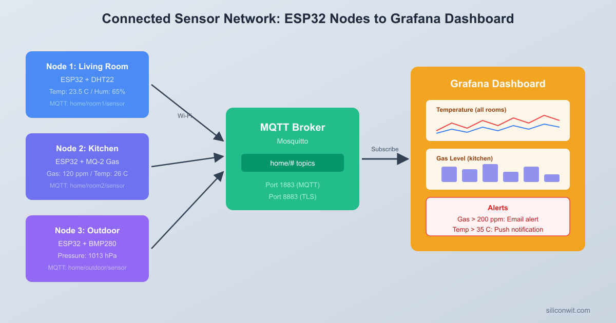
System Architecture
The system consists of two ESP32 nodes communicating through an MQTT broker. The outdoor sensor node is battery powered and spends most of its time in deep sleep. Every 5 minutes it wakes, reads three sensors (DHT22 for temperature and humidity, capacitive soil moisture via ADC, battery voltage via ADC with a voltage divider), connects to Wi-Fi, publishes all readings to the MQTT broker over TLS, checks for OTA firmware updates, and returns to deep sleep. The entire wake cycle takes about 5 to 8 seconds.
The indoor display node is USB powered and always on. It maintains a persistent MQTT connection, subscribes to the outdoor sensor topics, and renders live data on an SSD1306 OLED (128x64 pixels, I2C). It also runs an HTTP server on port 80 that serves a simple web dashboard showing the same readings in a browser. Both nodes register last will messages with the broker so that if either goes offline unexpectedly, the other (or any monitoring client) receives a notification.
Both nodes also pull OTA updates from a firmware HTTP server on your local network. The outdoor node checks once per wake cycle; the indoor node checks every hour.
MQTT Topic Design
A clean topic hierarchy keeps the system organized and makes it easy to add more sensor nodes later. All topics are nested under home/outdoor/ for this node:
home/outdoor/status → "online" / "outdoor-node-offline" (retained, last will)
Topic Design Decisions
Retained messages. Every data topic uses retained messages. This means a new subscriber (such as the indoor display node rebooting) immediately receives the last known values without waiting for the next sensor wake cycle. The status topic is also retained so that the last will message persists until the node comes back online and overwrites it with “online.”
QoS 1 (at least once). All publishes and subscriptions use QoS 1. QoS 0 would risk losing a reading if the TCP connection drops mid-publish, and the outdoor node cannot retry because it is about to enter deep sleep. QoS 2 (exactly once) adds extra round trips that increase wake time and battery drain. QoS 1 is the practical middle ground: the broker acknowledges receipt, and the occasional duplicate message is harmless for sensor data (the display simply shows the latest value).
Flat values, not JSON. Each topic carries a single numeric string. This is simpler to parse on the display node and avoids pulling in a JSON library. If you later need structured payloads (timestamps, units, node IDs), switching to JSON is straightforward.
Last will message. The outdoor node registers its last will on home/outdoor/status with the payload outdoor-node-offline, QoS 1, retained. When the node connects, it immediately publishes online to the same topic. If the node crashes or the network drops, the broker delivers the last will after the keep-alive timeout expires.
Circuit Connections
Outdoor Sensor Node Wiring
Outdoor Node (Battery Powered)
┌──────────────┐
│ ESP32 DevKit │
│ GP4 ├──┬──[R1 4.7K]── 3.3V
│ │ └── DHT22 Data
│ │
│ GP34 ├───── Soil Moisture AOUT
│ │
│ GP35 ├───┐
│ │ ├── Voltage Divider
│ GND ├──[100K]──┤──[100K]── Batt+
│ │ │
│ 3.3V ├── Batt+ (2xAA, 3.0V)
│ GND ├── Batt-
└──────────────┘
Connect the DHT22 sensor and soil moisture sensor to the ESP32 on a breadboard. The battery voltage is read through a resistor voltage divider so that the full battery range (0 to 4.2V for lithium, 0 to 3.3V for alkaline) maps into the ESP32’s ADC input range (0 to 3.3V). If you are using 2x AA alkaline batteries (3.0V nominal), the divider is optional since the voltage is already within range, but including it protects the ADC from any overshoot.
ESP32 Pin
Component
Notes
GPIO 4
DHT22 data pin
4.7k pull-up to 3.3V
3.3V
DHT22 VCC
Power supply
GND
DHT22 GND
Common ground
GPIO 34
Soil moisture sensor AOUT
ADC1_CHANNEL_6
3.3V
Soil moisture sensor VCC
Power supply
GND
Soil moisture sensor GND
Common ground
GPIO 35
Battery voltage divider midpoint
ADC1_CHANNEL_7
GND
Voltage divider bottom
Two 100k resistors
Battery +
Voltage divider top
Through 100k to GPIO 35
The voltage divider uses two 100k ohm resistors. The midpoint connects to GPIO 35. With this divider, a 3.0V battery reads as 1.5V at the ADC, and you multiply by 2 in software to get the true voltage.
Indoor Display Node Wiring
Indoor Node (USB Powered)
┌──────────────┐ ┌──────────────┐
│ ESP32 DevKit │ │ SSD1306 OLED │
│ │ │ 128x64 I2C │
│ GP21 (SDA) ─┼────┤ SDA │
│ GP22 (SCL) ─┼────┤ SCL │
│ 3.3V ───────┼────┤ VCC │
│ GND ────────┼────┤ GND │
│ │ └──────────────┘
│ MQTT sub ───┼── Live sensor data
│ HTTP :80 ───┼── Web dashboard
│ USB │
└──────┤├──────┘
ESP32 Pin
Component
Notes
GPIO 21 (SDA)
SSD1306 SDA
I2C data
GPIO 22 (SCL)
SSD1306 SCL
I2C clock
3.3V
SSD1306 VCC
Power supply (some modules need 5V, check yours)
GND
SSD1306 GND
Common ground
Most SSD1306 breakout boards have built-in pull-up resistors on SDA and SCL. If your display does not, add 4.7k pull-ups from each line to 3.3V. The I2C address for the SSD1306 is typically 0x3C. Some modules use 0x3D; check the silkscreen or datasheet for your board.
Outdoor Sensor Node Firmware
This is the complete main.c for the outdoor sensor node. It combines deep sleep (Lesson 8), MQTT with TLS (Lesson 5), ADC sensor reading (Lesson 2), and OTA updates (Lesson 7) into a single wake-publish-sleep cycle.
The code follows a linear flow: boot, read sensors, connect, publish, check OTA, sleep. There are no persistent tasks or event loops because the node is only awake for a few seconds. The RTC_DATA_ATTR variables (boot_count and msg_counter) survive deep sleep resets and let you track how many cycles the node has completed.
SSD1306 OLED Driver (I2C)
Before writing the indoor display node firmware, you need a way to drive the SSD1306 OLED over I2C. The driver below sends raw commands and pixel data to the display controller. It includes an in-memory framebuffer (1024 bytes for 128x64 pixels) and a built-in 5x7 pixel font for rendering text. This approach is similar to what you may have seen in the ATmega328P course with SPI, but here everything goes over I2C.
How the SSD1306 I2C Protocol Works
The SSD1306 uses a standard I2C interface with address 0x3C (or 0x3D on some boards). Every I2C write starts with a control byte that tells the display whether the following bytes are commands or data:
Control byte 0x00: the next byte is a command (single command mode).
Control byte 0x40: all following bytes are display data (GDDRAM pixel data).
The 128x64 display is organized into 8 pages of 128 columns. Each page is 8 pixels tall. One byte in the framebuffer represents a vertical column of 8 pixels within a page. So the full framebuffer is 128 x 8 = 1024 bytes.
ssd1306.h
Create this header in the indoor display node project at main/ssd1306.h:
Each character in the 5x7 font is stored as 5 bytes, where each byte represents one column of pixels. The ssd1306_text function walks through the string, looks up each character’s glyph, and sets the corresponding pixels in the framebuffer. After composing the full frame, a single call to ssd1306_update pushes all 1024 bytes to the display over I2C.
Indoor Display Node Firmware
The indoor display node is the second half of the system. It subscribes to the outdoor sensor topics, renders the data on the SSD1306 OLED, and serves a web dashboard. Unlike the outdoor node, this one runs continuously with multiple FreeRTOS tasks.
The indoor node runs four concurrent services: the MQTT client (managed by the ESP-MQTT library on its own task), the OLED display refresh task (1 Hz on core 1), the HTTP server (handled by the httpd component), and the OTA check task (runs on core 0, checks once per hour). All sensor data access goes through a mutex so that the display task, the HTTP handler, and the MQTT callback never corrupt each other’s reads and writes.
The web dashboard uses <meta http-equiv='refresh' content='5'> to auto-reload every 5 seconds. This avoids the need for JavaScript or WebSocket code. Anyone on the same network can open the ESP32’s IP address in a browser and see live sensor readings.
Building and Deploying
Step 1: Set Up the MQTT Broker
You can use any MQTT broker that supports TLS. SiliconWit IoT provides a broker for course projects, or choose one of these options:
When you rebuild a project with changes, copy the new binary to this directory. The next time a node checks for an OTA update, it will download and install the new firmware.
Step 5: Verify End-to-End
Power on the indoor display node via USB. The OLED should show “Connecting…” and then switch to the sensor display layout once Wi-Fi and MQTT are connected
Power on the outdoor sensor node with batteries. Watch the serial monitor (if connected) to confirm it reads sensors, connects to Wi-Fi, publishes to MQTT, and enters deep sleep
Within a few seconds, the indoor OLED should display the temperature, humidity, soil moisture, and battery voltage
Open a browser and navigate to the indoor node’s IP address (shown in the serial log). The web dashboard should display the same values
Wait 5 minutes for the next outdoor node wake cycle. The display should update and the “last update” counter should reset
Test the last will: disconnect the outdoor node’s battery. After the MQTT keep-alive timeout (15 seconds), the status on the display should change from “ON” to “OFF”
Testing with MQTT Command-Line Tools
You can also verify the MQTT topics using mosquitto_sub:
Terminal window
# Subscribe to all outdoor topics (use your broker's hostname and credentials)
mosquitto_sub-habc123.s1.eu.hivemq.cloud-p8883\
--cafilemqtt_server.pem\
-umyuser-Pmypassword\
-t"home/outdoor/#"-v
You should see messages like:
home/outdoor/status online
home/outdoor/temperature 23.5
home/outdoor/humidity 61.2
home/outdoor/soil 42
home/outdoor/battery 3.12
Production Readiness Checklist
Before deploying this system in a real environment (garden, greenhouse, rooftop), review each item in this checklist. The capstone code already handles many of these, but some require configuration or hardware decisions beyond the firmware.
Watchdog and Recovery
Item
Status in Capstone Code
Notes
Task watchdog on main task
Yes (both nodes)
Outdoor: 30s, indoor: 60s
Wi-Fi reconnection
Yes (event handler retries)
Outdoor: 5 retries then sleep. Indoor: 10 retries
MQTT auto-reconnect
Yes (ESP-MQTT library default)
Library reconnects automatically on disconnect
Sensor read failure handling
Yes (DHT22 retry, error values)
Publishes -999 if sensor fails, so dashboard shows something is wrong
Last will message
Yes (both nodes)
Broker publishes offline status if node disconnects ungracefully
OTA and Firmware Safety
Item
Status
Notes
Dual OTA partitions
Yes (partition table config)
Factory + OTA_0 + OTA_1
Rollback on failed boot
Yes (esp_ota_mark_app_valid)
New firmware must boot successfully or bootloader reverts
Version comparison before OTA
Partial
The esp_https_ota function checks the binary header. For strict version comparison, add a version endpoint on the OTA server
OTA over TLS
Configurable
Use https:// URL and embed the server certificate
Power and Battery
Item
Notes
Deep sleep current
Measure with a multimeter. ESP32 DevKitC has onboard USB-UART chip that draws extra current. For production, use a bare ESP32 module
Battery voltage monitoring
Included in firmware. Set a low-battery threshold (e.g., 2.2V for 2x AA) and publish a warning
Power supply decoupling
Add a 100uF capacitor near the ESP32 VIN pin to handle Wi-Fi transmit current spikes
Sensor power gating
For even lower sleep current, power the DHT22 and soil sensor through a GPIO or MOSFET so they draw zero current during sleep
Data Integrity and Storage
Item
Notes
NVS wear leveling
The ESP-IDF NVS library handles wear leveling automatically. Avoid writing to NVS on every wake cycle; use RTC memory for counters
Retained messages
All sensor topics use retained messages so that a rebooted subscriber gets the latest data immediately
Message ordering
QoS 1 guarantees delivery but not strict ordering. For sensor data this is acceptable because each message is timestamped by topic
Security
Item
Notes
TLS for MQTT
Configured in both nodes. Verify the broker certificate is correct
Flash encryption
Enable in development mode first (idf.py menuconfig, Security Features). This prevents reading firmware from the flash chip
Secure boot v2
Prevents flashing unauthorized firmware. Enable after flash encryption is working. See Lesson 7 for details
MQTT credentials
Stored in NVS via menuconfig. For production, use per-device certificates (X.509 client authentication) instead of shared passwords
Enclosure and Environment
Item
Notes
Weatherproof enclosure
Outdoor node needs an IP65 or better enclosure. Route the DHT22 sensor outside the enclosure through a vent
Antenna placement
Keep the ESP32 antenna away from metal surfaces and battery packs. Orient it vertically for best range
Temperature range
The ESP32 operates from -40 to 85 degrees Celsius. Batteries are the limiting factor; lithium cells perform better in cold weather than alkaline
Exercises
Exercise 1: Add a Third Node
Add a second outdoor sensor node (e.g., a different room or a balcony) that publishes to home/balcony/temperature, home/balcony/humidity, etc. Modify the indoor display node to cycle between outdoor and balcony readings every 3 seconds on the OLED, and add a second page to the web dashboard. You will need to subscribe to home/+/temperature using the MQTT single-level wildcard.
Exercise 2: Historical Data Logging
Add a circular buffer in the indoor node’s PSRAM (or regular RAM if no PSRAM) that stores the last 24 hours of temperature readings (one per 5-minute cycle = 288 entries). Serve a /history endpoint on the HTTP server that returns the buffer as a JSON array. Bonus: render a simple ASCII chart or a sparkline on the OLED showing the temperature trend over the last few hours.
Exercise 3: Alert Notifications
Add a threshold check in the indoor display node: if soil moisture drops below 20% or battery drops below 2.3V, publish an alert to home/outdoor/alert with QoS 2. Set up a phone app (such as MQTT Dashboard for Android or MQTTool for iOS) that subscribes to this alert topic and shows a push notification. Flash an indicator on the OLED when an alert is active.
Exercise 4: Encrypted Configuration
Store the Wi-Fi SSID, password, and MQTT credentials in NVS instead of hardcoding them in sdkconfig. Write a provisioning mode that starts a BLE GATT server (from Lesson 6) on the first boot, allowing you to configure credentials from a phone app. Once configured, the node reboots into normal operation. This removes the need to recompile firmware to change networks.
Summary
This capstone brought together every major topic from the course. The outdoor sensor node combines GPIO sensor reading (Lesson 2), Wi-Fi connectivity (Lesson 3), MQTT publishing with TLS (Lesson 5), deep sleep with RTC memory (Lesson 8), and OTA updates with rollback protection (Lesson 7). The indoor display node adds I2C peripheral driving, FreeRTOS multitasking, HTTP server hosting (Lesson 4), and continuous MQTT subscription. Together they form a complete IoT deployment that you can extend, harden, and adapt to real projects.
The key architectural decisions: keeping MQTT topics flat and retained for simplicity, using QoS 1 as the pragmatic middle ground, separating the two nodes so each can be updated and debugged independently, and building in offline detection through last will messages. These patterns apply whether you are monitoring a garden, a greenhouse, an industrial process, or a building HVAC system.
From here, the exercises point toward the kinds of extensions you will encounter in production: multi-node networks, historical data, alerting, and secure provisioning. Each of those builds directly on the foundation this course has established.
Comments