Every microcontroller has timer/counter peripherals, and they are among the most heavily used features in embedded programming. PWM for motor control, input capture for frequency measurement, periodic interrupts for task scheduling: they all depend on hardware counters. This lesson shows you how counters work at the flip-flop level, so that when you configure TIM2 on an STM32 or Timer1 on an ATmega328P, you understand exactly what the silicon is doing. #Counters #Timers #FrequencyDividers
What Is a Counter?
A counter is a sequential circuit that goes through a predetermined sequence of states on each clock pulse. The simplest counter increments by one on each pulse, cycling through binary values: 0, 1, 2, 3, …, back to 0.
A counter is built from flip-flops. Each flip-flop stores one bit of the count value. An -bit counter uses flip-flops and counts from 0 to .
Counter Width
Flip-Flops
Count Range
Typical Use
4-bit
4
0 to 15
BCD counting, simple dividers
8-bit
8
0 to 255
Timer0 on ATmega328P
16-bit
16
0 to 65,535
Timer1 on ATmega328P, general-purpose timers
32-bit
32
0 to 4,294,967,295
TIM2/TIM5 on STM32, system tick counters
Ripple Counter (Asynchronous)
How It Works
The simplest counter connects flip-flops in a chain where the output of each flip-flop drives the clock of the next. Each flip-flop is in toggle mode (for JK flip-flops: J=K=1; for D flip-flops: ).
Each flip-flop toggles on the falling edge of the previous flip-flop’s output. When Q0 transitions from 1 to 0, it triggers FF1 to toggle.
Counting Sequence
Clock Pulse
Q3
Q2
Q1
Q0
Decimal
0
0
0
0
0
0
1
0
0
0
1
1
2
0
0
1
0
2
3
0
0
1
1
3
4
0
1
0
0
4
5
0
1
0
1
5
6
0
1
1
0
6
7
0
1
1
1
7
8
1
0
0
0
8
9
1
0
0
1
9
10
1
0
1
0
10
11
1
0
1
1
11
12
1
1
0
0
12
13
1
1
0
1
13
14
1
1
1
0
14
15
1
1
1
1
15
16
0
0
0
0
0 (overflow)
After reaching 15, the counter rolls over to 0. This rollover is called overflow, and in an MCU timer, it can generate an interrupt.
The “Ripple” Problem
The term “ripple” refers to the propagation delay issue. Each flip-flop must wait for the previous one to toggle before it can respond. In a 4-bit counter, the worst-case delay is four flip-flop propagation delays.
For a 74HC flip-flop at 5V, the propagation delay is about 10 ns. A 4-bit ripple counter has up to 40 ns of total delay. An 8-bit counter has up to 80 ns. A 32-bit counter built this way would have up to 320 ns of ripple delay, which limits the maximum clock frequency.
During the ripple period, the output bits are in an intermediate state and do not represent a valid count. This is called a “glitch” and can cause problems if the counter value is being read by other logic.
Synchronous Counter
How It Works
A synchronous counter solves the ripple problem by clocking all flip-flops simultaneously from the same clock signal. Additional logic determines which flip-flops should toggle on each clock edge.
The rule for a binary up-counter:
FF0 toggles on every clock pulse
FF1 toggles when Q0 = 1 (all lower bits are 1)
FF2 toggles when Q0 = 1 AND Q1 = 1
FFn toggles when Q0 AND Q1 AND … AND Q(n-1) are all 1
The toggle condition for each flip-flop is an AND of all lower-order outputs.
4-bit synchronous counter logic:
CLK ──→ [FF0] [FF1] [FF2] [FF3]
│ │ │ │
Q0 Q1 Q2 Q3
Toggle enables:
FF0: always toggle
FF1: toggle when Q0 = 1
FF2: toggle when Q0·Q1 = 1
FF3: toggle when Q0·Q1·Q2 = 1
All flip-flops see the clock edge simultaneously, so all outputs update at the same time. No ripple, no glitches. This is how real MCU timers work.
Tradeoff: Speed vs. Gates
Property
Ripple Counter
Synchronous Counter
Clock distribution
Each FF clocked by previous FF
All FFs share one clock
Output glitches
Yes (during ripple)
No
Maximum frequency
Limited by total ripple delay
Limited by single FF delay + AND gate
Gate count
Minimal (just flip-flops)
More gates (AND chain for toggle enables)
Used in real MCUs
Rarely
Always
Up/Down Counter
Concept
An up/down counter can count in either direction, controlled by a direction input. When DIR = 0, the counter increments; when DIR = 1, it decrements.
4-bit up/down count sequence (starting at 5):
Clock
DIR
Count
0
-
5
1
0 (up)
6
2
0 (up)
7
3
1 (down)
6
4
1 (down)
5
5
1 (down)
4
Implementation
The difference between up and down counting is which output drives the toggle logic: for up counting, use Q outputs; for down counting, use outputs. A multiplexer selects between Q and based on the DIR input.
In MCU Timers
Most MCU timers support up/down counting. The STM32 general-purpose timers (TIM2-TIM5) can be configured for:
Up counting: 0 to auto-reload value, then overflow interrupt and restart
Down counting: auto-reload value to 0, then underflow interrupt and restart
Center-aligned (up/down): count up to auto-reload, then back down to 0; generates symmetric PWM
The center-aligned mode is particularly useful for motor control PWM because it produces symmetric waveforms that reduce current ripple.
Frequency Dividers and Prescalers
Concept
A single toggle flip-flop divides its input frequency by 2. The output Q changes state on every clock edge, so Q completes one full cycle for every two input cycles.
Input:  ┌─┐ ┌─┐ ┌─┐ ┌─┐ ┌─┐ ┌─┐ ┌─┐ ┌─┐        │ │ │ │ │ │ │ │ │ │ │ │ │ │ │ │     ───┘ └─┘ └─┘ └─┘ └─┘ └─┘ └─┘ └─┘ └───
Q0:     ┌───┐   ┌───┐   ┌───┐   ┌───┐        │   │   │   │   │   │   │   │     ───┘   └───┘   └───┘   └───┘   └──────   (f/2)
Q1:     ┌───────┐       ┌───────┐        │       │       │       │     ───┘       └───────┘       └──────────   (f/4)
Q2:     ┌───────────────┐        │               │     ───┘               └─────────────────   (f/8)
  Prescaler chain (frequency divider)
  72 MHz          36 MHz   18 MHz    9 MHz  Input ──→[FF0]──→[FF1]──→[FF2]──→[FF3]──→     │       /2       /2       /2       /2     │     └──→ 4.5 MHz   2.25 MHz  1.125 MHz          [FF4]──→[FF5]──→[FF6]──→ ...            /2       /2       /2
  A MUX selects which stage feeds  the timer (programmable prescaler).
A chain of toggle flip-flops divides the frequency by :
Flip-Flops
Division Factor
Example: 72 MHz input
1
/2
36 MHz
2
/4
18 MHz
3
/8
9 MHz
4
/16
4.5 MHz
8
/256
281.25 kHz
16
/65,536
1,098.6 Hz
Prescalers in MCU Timers
This is exactly what a prescaler does. When you configure an MCU timer prescaler:
The prescaler is a programmable counter that divides the input clock. The “+1” in the formula accounts for the counter starting at 0. A prescaler value of 0 means no division (divide by 1).
On the ATmega328P:
// Set Timer0 prescaler to /64
TCCR0B |= (1<< CS01) | (1<< CS00);
The prescaler select bits choose from a fixed set of division factors: 1, 8, 64, 256, 1024. These are implemented as a multiplexer that selects which stage of a ripple counter chain provides the timer clock.
Modulo-N Counters
A 4-bit counter naturally counts to 16 (modulo 16). But what if you need a different count? A modulo-N counter resets to 0 when it reaches N.
Example: Modulo-10 (BCD) counter
Use a 4-bit counter with a reset circuit. When the count reaches 1010 (decimal 10), a decoder detects this pattern and asserts the asynchronous reset:
Q3·Q1 = 1 only when count = 10 (1010) or 11 (1011) or 14 (1110) or 15 (1111)
For a BCD counter, detecting is sufficient because the counter will reset so fast that it never reaches 11. The brief glitch at count 10 lasts only a few nanoseconds before the reset takes effect.
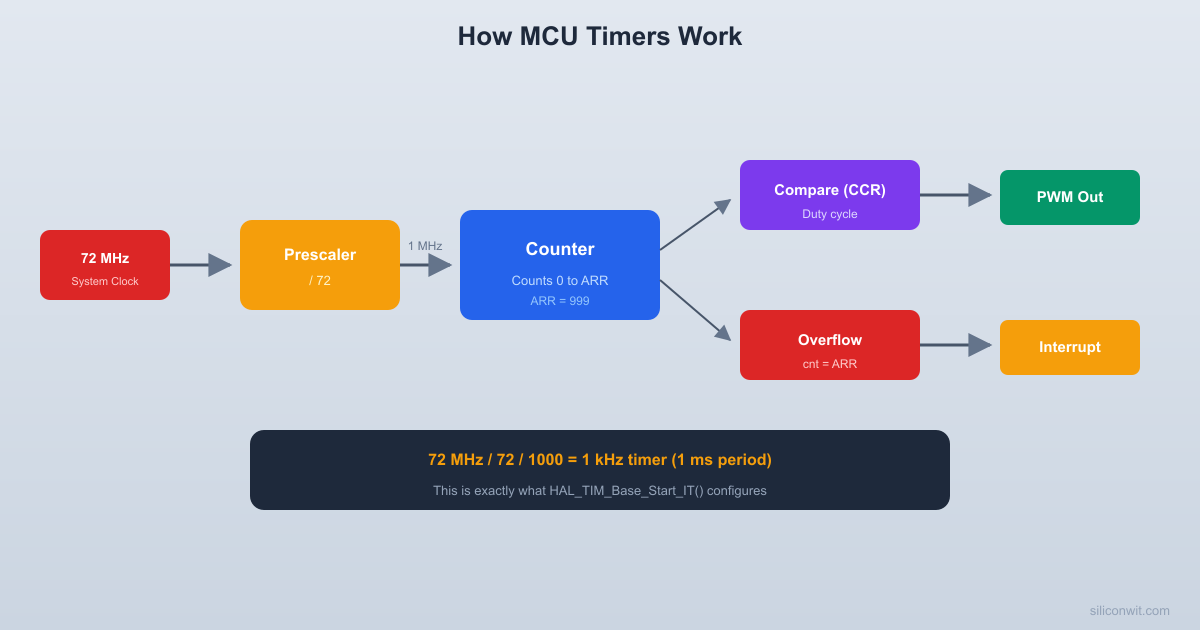
In MCU timers, the auto-reload register serves this purpose. Setting TIM2->ARR = 999 makes the timer count from 0 to 999 and then reset (modulo-1000 counter).
  MCU Timer block diagram (simplified)
  System    ┌───────────┐  Timer   ┌──────────┐  Clock ───→│ Prescaler │  Clock  │  Counter  │  (72MHz)   │ (PSC reg) ├────────→│  (CNT)   │            └───────────┘         └────┬─────┘                                       │ compare                              ┌────────┴────────┐                              │  =ARR?   =CCR?  │                              └───┬────────┬────┘                                  │        │                             Overflow   Compare                             Interrupt  Match/PWM
The 74HC393: Dual 4-Bit Binary Counter
Overview
The 74HC393 contains two independent 4-bit binary ripple counters in a single 14-pin DIP package.
74HC393
┌────┐
1A ─┤1 14├─ VCC
1QA ─┤2 13├─ 2A
1QB ─┤3 12├─ 2QA
1QC ─┤4 11├─ 2QB
1QD ─┤5 10├─ 2QC
MR ─┤6 9├─ 2QD
GND ─┤7 8├─ 2MR
└────┘
Pin
Function
1A
Clock input for counter 1 (falling-edge triggered)
2-5
Outputs QA through QD (counter 1)
6
Master Reset for counter 1 (active high)
13
Clock input for counter 2
12-9
Outputs QA through QD (counter 2)
8
Master Reset for counter 2
You can cascade the two counters by connecting 1QD (pin 5) to 2A (pin 13), creating an 8-bit ripple counter.
Practical: Build a 4-Bit Counter with LEDs
Parts Needed
Component
Quantity
74HC393
1
LEDs
4
220 ohm resistors
4
Push button
1
10K resistor (pull-up)
1
0.1 uF capacitor (debounce)
1
Breadboard, jumper wires, 5V supply
1 set
Wiring
Place the 74HC393 on the breadboard.
Power: pin 14 to 5V, pin 7 to GND.
Master Reset (pin 6) to GND through a 10K resistor, so it stays low (not reset) during normal operation. You can add a push button from pin 6 to 5V for manual reset.
Clock input (pin 1): connect a push button. Wire the button between pin 1 and GND. Add a 10K pull-up resistor from pin 1 to 5V. The counter increments on each falling edge (when you press the button). Add a 0.1 uF capacitor across the button for hardware debouncing.
Connect LEDs to outputs:
QA (pin 2) through 220 ohm to LED 0 (LSB)
QB (pin 3) through 220 ohm to LED 1
QC (pin 4) through 220 ohm to LED 2
QD (pin 5) through 220 ohm to LED 3 (MSB)
Test: Press the clock button repeatedly. The LEDs should count in binary: 0000, 0001, 0010, 0011, …, 1111, 0000 (overflow back to 0).
Observing the Count
As you press the button, watch the LED pattern. You will see:
LED 0 (QA) toggles on every press
LED 1 (QB) toggles on every other press
LED 2 (QC) toggles every 4 presses
LED 3 (QD) toggles every 8 presses
This is binary counting. After 16 button presses, all LEDs return to off (counter overflow).
Practical: Frequency Divider
Using the 74HC393 as a Divider
Connect the two halves of the 74HC393 in cascade for an 8-bit divider:
Feed a clock signal into pin 1. This could be from a function generator, a 555 timer circuit, or an MCU pin toggling at a known frequency.
Observe the outputs:
1QA (pin 2): input frequency / 2
1QB (pin 3): input frequency / 4
1QC (pin 4): input frequency / 8
1QD (pin 5): input frequency / 16
2QA (pin 12): input frequency / 32
2QB (pin 11): input frequency / 64
2QC (pin 10): input frequency / 128
2QD (pin 9): input frequency / 256
If you feed in 1 kHz, pin 9 outputs approximately 3.9 Hz (1000 / 256), which is slow enough to see an LED blink.
Exercises
Exercise 1: Counter Timing
A 4-bit synchronous counter runs at 10 MHz. How long does it take to count from 0 to 15 and overflow back to 0?
Solution
The counter needs 16 clock pulses to go from 0 back to 0. At 10 MHz, each clock period is 100 ns. Total time: .
Exercise 2: Prescaler Calculation
Your MCU runs at 72 MHz. You need a timer that overflows every 1 ms (1 kHz overflow rate). The timer is 16-bit (counts 0 to 65,535). What prescaler and auto-reload value would you use?
Solution
Timer clock after prescaler:
Overflow period:
We want .
Choose PSC = 71:
Then:
So .
Timer counts from 0 to 999 at 1 MHz, overflowing every 1 ms.
TIM2->PSC =71;
TIM2->ARR =999;
Exercise 3: Frequency Division
You have a 32.768 kHz crystal oscillator (commonly used for RTC). How many divider stages do you need to get a 1 Hz signal?
Solution
You need 15 divider stages (15 flip-flops) to divide 32,768 Hz down to 1 Hz. This is exactly why 32.768 kHz crystals are used for real-time clocks: a 15-bit binary counter produces a perfect 1 Hz output.
How This Connects to Embedded Programming
Timer/Counter Peripherals
Every MCU timer is a synchronous counter with a programmable prescaler (frequency divider), auto-reload register (modulo-N counter), and compare registers (for PWM). When you write TIM2->PSC = 71; TIM2->ARR = 999;, you are configuring a hardware counter exactly like the circuits in this lesson.
PWM Generation
PWM is a counter compared against a threshold. The counter counts up from 0 to ARR. When the count is below the compare value, the output is high; above it, the output is low. Changing the compare value changes the duty cycle. The counter and comparator are the hardware doing the work.
Input Capture
Input capture uses a free-running counter. When an external signal edge arrives, the current counter value is latched into a capture register. By comparing two consecutive captures, you measure the time between edges (and therefore the frequency or pulse width).
The SysTick Timer
ARM Cortex-M processors include a 24-bit SysTick counter that typically generates a 1 ms interrupt for the operating system tick. It is a down-counter that reloads when it reaches zero. HAL_Delay(100) counts 100 SysTick interrupts, each generated by this hardware counter reaching zero.
Summary
Concept
Key Takeaway
Ripple counter
Simple chain of toggle flip-flops. Output ripples create glitches.
Synchronous counter
All flip-flops clocked together. No glitches. Used in real MCUs.
Up/down counter
Counts in either direction. MCU timers support up, down, and center-aligned modes.
Frequency divider
Each flip-flop stage divides by 2. A prescaler is a programmable divider.
Modulo-N counter
Resets at a chosen count. MCU auto-reload register sets the modulus.
74HC393
Dual 4-bit ripple counter IC. Cascadable to 8 bits.
In the next lesson, you will explore memory: how SRAM cells store your variables, how Flash stores your program, and how the MCU’s memory map organizes everything into a unified address space.
Comments