Motors, servos, and buzzers all need precisely timed electrical signals to function correctly. The STM32’s hardware timers generate those signals autonomously, freeing the CPU to handle sensor reads, communication, and logic. In this lesson you will configure multiple timer channels for PWM output, drive servos to exact angles, control DC motor speed through an H-bridge, play tones on a passive buzzer, and measure external signal frequencies with input capture. Two potentiometers tie it all together: one controls pan, the other controls tilt, and a button toggles the DC motor with a smooth speed ramp. #STM32 #PWM #MotorControl
What We Are Building
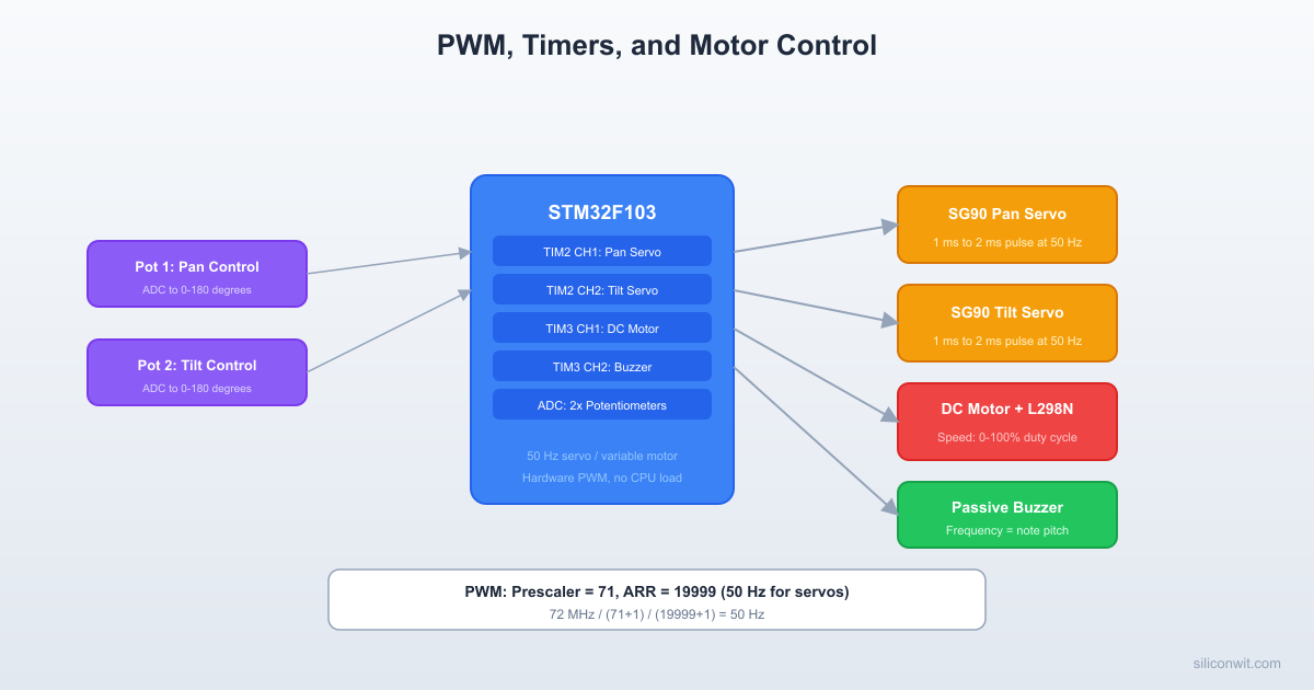
Servo Pan-Tilt Mount with DC Motor Speed Control
A two-axis servo mount where potentiometer 1 controls the pan servo (0 to 180 degrees) and potentiometer 2 controls the tilt servo (0 to 180 degrees). A push button toggles a DC motor on and off with a gradual speed ramp through an L298N H-bridge. When either servo reaches its travel limit (0 or 180 degrees), a passive buzzer plays a short warning tone. All PWM generation runs in timer hardware with minimal CPU overhead.
Project specifications:
Parameter
Value
Board
Blue Pill (STM32F103C8T6)
Pan servo
SG90 on PA0 (TIM2_CH1)
Tilt servo
SG90 on PA1 (TIM2_CH2)
DC motor PWM
PA6 (TIM3_CH1) to L298N ENA
DC motor direction
PB0 (IN1), PB1 (IN2)
Buzzer
PA7 (TIM3_CH2)
Pot 1 (pan)
PA2 (ADC1_CH2)
Pot 2 (tilt)
PA3 (ADC1_CH3)
Button
PB10 (GPIO input, internal pull-up)
Serial output
USART1 on PA9/PA10 (115200 baud)
Bill of Materials
Component
Quantity
Notes
Blue Pill (STM32F103C8T6)
1
WeAct version recommended
ST-Link V2 clone
1
SWD programmer/debugger
SG90 micro servo
2
4.8 to 6V operating, pan and tilt
DC motor (3 to 6V)
1
Small brushed motor
L298N motor driver module
1
Dual H-bridge, only one channel used
Potentiometer (10K)
2
Analog input for servo position
Passive buzzer
1
PWM-driven tone generation
Push button
1
Motor on/off toggle
Breadboard + jumper wires
1 set
Assorted lengths
External 5V supply
1
For servos if USB current is insufficient
Timer PWM Fundamentals
The STM32F103 timers generate PWM by comparing a free-running counter against a threshold value. The counter counts from 0 up to the auto-reload register (ARR), then resets. On each count, the hardware compares the counter against the capture/compare register (CCR) for each channel and sets the output pin high or low accordingly.
Auto-reload: the counter counts from 0 to ARR, then resets. Period = (ARR + 1) / counter_clock
CCRx
Capture/compare for channel x: sets the duty cycle threshold
CCMR1/2
Output compare mode selection per channel
CCER
Channel enable and polarity
PWM Mode 1 vs Mode 2
In PWM mode 1, the output is high when the counter is less than CCR and low otherwise. In PWM mode 2, the polarity is inverted: low when counter is less than CCR, high otherwise. For servos and motor drivers that expect active-high signals, PWM mode 1 is the standard choice.
Prescaler and ARR Calculation
For a 50 Hz servo signal (20 ms period) with 1 microsecond resolution:
Parameter
Calculation
Value
Timer clock
System clock
72 MHz
PSC
72 MHz / 1 MHz target = 72
71
Counter clock
72 MHz / (71 + 1)
1 MHz (1 us per tick)
ARR
20 ms / 1 us = 20000
19999
CCR for 0 degrees
0.5 ms / 1 us
500
CCR for 90 degrees
1.5 ms / 1 us
1500
CCR for 180 degrees
2.5 ms / 1 us
2500
 Servo PWM Signal (50 Hz, 20 ms period) 0 deg:  0.5ms       180 deg:  2.5ms ┌──┐                 ┌──────────┐ │  │                 │          │ │  └────────────     │          └──── |<-- 20 ms --->|     |<-- 20 ms --->|
 L298N H-Bridge Motor Control ┌────────────────────────────────┐ │         L298N Module           │ │  IN1 ──> Motor direction A     │ │  IN2 ──> Motor direction B     │ │  ENA ──> PWM speed control     │ │          ┌───────────┐        │ │  Motor ──┤ H-Bridge  ├── Motor│ │  (+)     │ IN1  IN2  │  (-)  │ │          │ H    L =FWD│       │ │          │ L    H =REV│       │ │          │ L    L =STOP│      │ │          └───────────┘        │ └────────────────────────────────┘
CubeMX Timer Configuration
Open STM32CubeIDE, create a new project for the STM32F103C8Tx, and configure the peripherals in the CubeMX graphical editor.
TIM2 Setup (Servos)
In the Pinout view, click on TIM2 in the left panel. Set Channel 1 to “PWM Generation CH1” and Channel 2 to “PWM Generation CH2”. CubeMX assigns PA0 and PA1 automatically.
Switch to the Configuration tab. Under Counter Settings, set Prescaler to 71 and Counter Period (ARR) to 19999. This gives a 50 Hz PWM with 1 us resolution.
For Channel 1 and Channel 2, set Mode to “PWM mode 1”, Pulse (initial CCR) to 1500 (90 degrees center), and CH Polarity to “High”.
Enable auto-reload preload (ARPE) under Counter Settings. This ensures ARR changes take effect at the next update event rather than mid-cycle.
TIM3 Setup (Motor PWM and Buzzer)
Set TIM3 Channel 1 to “PWM Generation CH1” (PA6, motor speed) and Channel 2 to “PWM Generation CH2” (PA7, buzzer).
For the motor PWM on Channel 1: Prescaler = 71, Counter Period = 999. This gives a 1 kHz PWM with 0.1% duty cycle resolution (1000 steps from 0 to 999). CCR range: 0 (stopped) to 999 (full speed).
For the buzzer on Channel 2: the buzzer shares the same timer base, so both channels have the same frequency initially. To change the buzzer frequency for tones, you will modify TIM3 ARR dynamically in code. Set initial Pulse to 0 (buzzer off).
Set both channels to PWM mode 1 with High polarity.
ADC1 Setup (Potentiometers)
Enable ADC1 with IN2 (PA2) and IN3 (PA3) in scan conversion mode. Set the number of conversions to 2.
In the rank configuration, set Rank 1 to Channel 2 (pan pot) and Rank 2 to Channel 3 (tilt pot). Set sampling time to 71.5 cycles for both (good balance of speed and accuracy).
Enable “Continuous Conversion Mode” and “Scan Conversion Mode”. Disable DMA for now; we will poll the values in the main loop.
GPIO Setup
Set PB0 and PB1 as GPIO_Output (motor direction: IN1 and IN2 on the L298N).
Set PB10 as GPIO_Input with internal pull-up enabled (button, active low).
Enable USART1 in asynchronous mode at 115200 baud (PA9 TX, PA10 RX) for serial debug output.
Wiring
Pan-Tilt + Motor Control Wiring
┌──────────────┐
│ Blue Pill │
│ │
│ PA0 (TIM2)─┼──── Pan Servo (SG90)
│ PA1 (TIM2)─┼──── Tilt Servo (SG90)
│ │
│ PA2 (ADC) ─┼──── Pot 1 (pan knob)
│ PA3 (ADC) ─┼──── Pot 2 (tilt knob)
│ │ ┌──────────┐
│ PA6 (TIM3)─┼────>│L298N ENA │
│ PB0 ───────┼────>│ IN1 ├── Motor
│ PB1 ───────┼────>│ IN2 ├── (+/-)
│ │ │ 12V in │
│ PA7 (TIM3)─┼──── │Buzzer │
│ PB10 ──────┼──┤BTN├ GND │
└──────────────┘ └──────────┘
STM32 Pin
Connects To
Function
PA0
Pan servo signal (orange wire)
TIM2_CH1 PWM
PA1
Tilt servo signal (orange wire)
TIM2_CH2 PWM
PA2
Pot 1 wiper (middle pin)
ADC1_CH2, pan input
PA3
Pot 2 wiper (middle pin)
ADC1_CH3, tilt input
PA6
L298N ENA pin
TIM3_CH1, motor speed PWM
PA7
Passive buzzer positive pin
TIM3_CH2, tone output
PA9
USB-Serial RX (for debug)
USART1_TX
PB0
L298N IN1
Motor direction A
PB1
L298N IN2
Motor direction B
PB10
Push button (other side to GND)
Motor toggle, pulled up internally
3.3V
Pot 1 and Pot 2 top pins
ADC reference
GND
Pot 1 and Pot 2 bottom pins, button, buzzer GND
Common ground
5V
Servo VCC (red wires), L298N 5V logic
Servo and logic power
GND
Servo GND (brown wires), L298N GND
Common ground
Ext 12V
L298N motor power input (VS)
Motor power (or 5 to 6V for small motors)
Servo Motor Control
Standard hobby servos use a 50 Hz PWM signal where the pulse width encodes the target angle. The SG90 accepts:
Pulse Width
Angle
0.5 ms (500 us)
0 degrees
1.0 ms (1000 us)
45 degrees
1.5 ms (1500 us)
90 degrees (center)
2.0 ms (2000 us)
135 degrees
2.5 ms (2500 us)
180 degrees
The mapping is linear: pulse_us = 500 + (angle * 2000) / 180.
DC Motor with H-Bridge
The L298N H-bridge controls motor direction and speed:
IN1
IN2
ENA (PWM)
Motor Action
HIGH
LOW
PWM duty
Forward at duty% speed
LOW
HIGH
PWM duty
Reverse at duty% speed
LOW
LOW
any
Coast (free spin)
HIGH
HIGH
any
Brake (short circuit motor terminals)
Speed control: the PWM duty cycle on ENA determines the effective voltage applied to the motor. At 50% duty, the motor receives roughly half the supply voltage (averaged). The 1 kHz PWM frequency on TIM3_CH1 is above the audible range for most motors, reducing whine.
Passive Buzzer Tones
A passive buzzer contains no internal oscillator. It produces sound at whatever frequency you drive it. To play a musical note, change the TIM3 period (ARR) to match the note frequency and set the duty cycle to 50% for maximum volume.
Note
Frequency (Hz)
ARR value (1 MHz clock)
C4
262
3816
D4
294
3401
E4
330
3030
F4
349
2865
G4
392
2551
A4
440
2272
B4
494
2024
C5
523
1912
To play a tone: set TIM3->ARR to the note value and TIM3->CCR2 to ARR/2 (50% duty). To stop: set TIM3->CCR2 to 0.
Input Capture
Timer input capture mode records the counter value when an external signal edge arrives. This lets you measure the period (and thus frequency) of an external signal without software polling. The STM32 latches the counter into the CCR register on the configured edge and optionally triggers an interrupt.
For this lesson, input capture is demonstrated as a debugging tool: you can measure the actual servo PWM frequency coming out of your own timer to verify the configuration, or measure an external signal from another device.
To configure TIM4_CH1 (PB6) as input capture in CubeMX: set Channel 1 to “Input Capture direct mode”, select rising edge, no prescaler, and no filter. Enable the TIM4 capture/compare interrupt in NVIC.
Complete Project Code
The following code goes into main.c inside the CubeIDE-generated project. The CubeMX initialization handles all peripheral setup. This code goes in the user sections that CubeMX preserves during regeneration.
main.c
/* USER CODE BEGIN Includes */
#include<stdio.h>
#include<string.h>
/* USER CODE END Includes */
/* USER CODE BEGIN PV */
/* Servo parameters */
#defineSERVO_MIN_PULSE500 /* 0.5 ms = 0 degrees */
#defineSERVO_MAX_PULSE2500 /* 2.5 ms = 180 degrees */
#defineSERVO_CENTER1500 /* 1.5 ms = 90 degrees */
/* Motor parameters */
#defineMOTOR_PWM_MAX999 /* TIM3 ARR for motor */
#defineMOTOR_RAMP_STEP10 /* Duty increment per ramp tick */
#defineMOTOR_RAMP_DELAY20 /* ms between ramp steps */
To measure an external signal frequency using TIM4 input capture, add the following to your project. Configure TIM4_CH1 (PB6) as input capture in CubeMX and enable the TIM4 global interrupt.
Flash and connect. Build the project, flash via ST-Link, and open a serial terminal at 115200 baud. You should see the startup beeps and status messages appearing every 500 ms.
Test servos. Rotate potentiometer 1 fully in each direction. The pan servo should sweep from 0 to 180 degrees. Repeat with potentiometer 2 for the tilt servo. When either pot reaches the end of travel, you should hear a short beep.
Test DC motor. Press the button. The motor should ramp up smoothly to 70% speed over about 1.5 seconds. Press again; the motor ramps down to a stop. The direction pins PB0/PB1 can be swapped in code to reverse rotation.
Verify with a multimeter or oscilloscope. Measure the PWM signal on PA0: you should see a 50 Hz waveform with the pulse width changing as you turn the pot. On PA6, verify the 1 kHz motor PWM and confirm the duty cycle matches the serial output percentage.
Test input capture. If you have a signal generator or a second timer output, connect it to PB6 and read ic_frequency over the serial terminal to verify the measurement.
Production Notes
Servo jitter. The SG90 can exhibit visible jitter if the PWM signal has timing noise. Common causes: interrupt handlers that run too long during a PWM update, or electrical noise on the signal line. Solutions include using hardware dead-time insertion (available on TIM1), adding a 100 nF capacitor on the servo signal line close to the servo connector, and keeping servo wires away from motor power wires.
Motor EMI. Brushed DC motors generate significant electrical noise when commutating. A 100 nF ceramic capacitor across the motor terminals reduces radiated emissions. For the L298N, add 100 nF ceramic capacitors on the power input as close to the driver IC as possible. If the STM32 resets when the motor starts, the power supply cannot handle the inrush current: add a bulk capacitor (100 to 470 uF electrolytic) on the motor power rail.
Power supply isolation. In a production design, the MCU power domain should be isolated from the motor power domain. Use separate voltage regulators for logic (3.3V) and motor power (5 to 12V). Connect the grounds at a single point to avoid ground loops. The L298N module already provides some isolation through its onboard regulator, but for high-current motors you should add your own regulation. For more on regulator selection, filtering, and multi-rail design, see Analog Electronics: Power Supply Design.
Timer resource allocation. The STM32F103C8T6 has four general-purpose timers (TIM2, TIM3, TIM4) and one advanced timer (TIM1). In this project, TIM2 handles servos and TIM3 handles the motor and buzzer. For a production version where motor and buzzer need independent frequencies, allocate them to separate timers. TIM4 is free for input capture or other uses.
Soft start for motors. The ramp function in this project prevents inrush current spikes that could cause brown-outs. In production firmware, implement the ramp with a timer interrupt rather than polling in the main loop to ensure consistent acceleration regardless of other processing delays.
Comments