The previous eight lessons taught you to cross-compile, build custom kernels, write device trees, develop kernel modules, create Buildroot and Yocto images, and manage system services. In this final lesson, you combine all of those skills into a single deployable product: an edge gateway that collects sensor data from the MCU nodes you built in the ESP32, RPi Pico, and STM32 courses, stores it locally, serves a live dashboard, and forwards selected data to the cloud. This project does things that microcontrollers cannot handle and does them more reliably than stock Raspberry Pi OS ever could in a deployed environment. #EdgeGateway #EmbeddedLinux #IoT
Edge Gateway Architecture
──────────────────────────────────────────
Sensor Nodes RPi Zero 2 W
──────────── ──────────────────
┌──────────┐ WiFi ┌──────────────┐
│ ESP32 ├──MQTT────►│ Mosquitto │
│ BME280 │ │ (broker) │
└──────────┘ └──────┬───────┘
┌──────────┐ WiFi │
│ Pico W ├──MQTT────► ├──► SQLite DB
│ Light │ ├──► Flask Dashboard
└──────────┘ ├──► Camera trigger
┌──────────┐ WiFi └──► Cloud bridge
│ STM32+ ├──MQTT────► (MQTT fwd)
│ ESP-01 │
└──────────┘
What We Are Building
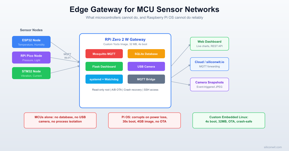
Edge Gateway: RPi Zero 2 W as MCU Network Hub
A complete edge gateway running on a custom Yocto image for the Raspberry Pi Zero 2 W. The gateway runs a Mosquitto MQTT broker that receives sensor data from ESP32 and RPi Pico nodes over Wi-Fi. Incoming readings are stored in a SQLite database (capable of holding months of history). A Python Flask web server provides live charts via Chart.js. A USB webcam capture service takes snapshots when sensor thresholds are exceeded. An MQTT bridge forwards aggregated data to a cloud broker. All services are managed by systemd with watchdog recovery.
System specifications:
Parameter
Value
Gateway hardware
Raspberry Pi Zero 2 W (BCM2710A1, Cortex-A53, AArch64)
Base image
Custom Yocto (Scarthgap) from Lesson 8’s meta-siliconwit-rpi
Subscribes to MQTT topics, writes to SQLite, triggers camera
gateway-dashboard
5000
Flask web server with live charts and REST API
gateway-camera
(triggered)
Captures JPEG snapshots on threshold events
mosquitto-bridge
(outbound)
Forwards selected topics to cloud broker
Gateway Data Flow
──────────────────────────────────────────
MQTT msg in ──► Mosquitto (port 1883)
│
┌────────────┼────────────┐
▼ ▼ ▼
gateway- gateway- mosquitto-
datalogger dashboard bridge
│ │ │
▼ ▼ ▼
SQLite DB Flask+Chart.js Cloud broker
(local (port 5000) (remote MQTT)
history) │
│ ▼
│ Browser
│
▼ threshold exceeded?
gateway-camera
│
▼
JPEG snapshot saved
Why This Cannot Run on a Microcontroller
The ESP32, STM32, and RPi Pico are excellent sensor nodes, but they cannot serve as a full gateway. Here is a concrete comparison of what this gateway does versus what a microcontroller can realistically handle:
Capability
RPi Zero 2 W Gateway
Typical MCU (ESP32/STM32/Pico)
SQLite database (months of data)
Yes, filesystem + 512 MB RAM
No filesystem or RAM for SQL engine
HTTP server with HTML templating
Flask with Jinja2, Chart.js
Basic HTTP possible, no templating engine
USB webcam capture
USB host + v4l2 + fswebcam
No USB host stack, no camera drivers
Run multiple isolated services
systemd process isolation
Single firmware, no process isolation
SSH remote access
Full OpenSSH server
No SSH, only serial or basic telnet
Python runtime
CPython 3.x with pip packages
MicroPython (limited), no pip
Log rotation and storage
journald + logrotate on ext4
Limited flash, no log rotation
OTA with rollback
A/B root partitions (Lesson 8)
Basic OTA, risky rollback
TLS certificate management
OpenSSL with full cert store
Minimal TLS, limited cert storage
The RPi Zero 2 W sits at the boundary between microcontrollers and full servers. It has enough resources to run Linux with real services, but it draws under 1 W at idle, costs under 20 USD, and fits in the same enclosures as an MCU board.
Why Not Just Use Raspberry Pi OS?
You could install Raspberry Pi OS, apt install mosquitto python3-flask, and build this gateway in an afternoon. So why spend eight lessons learning to build a custom image? Because Raspberry Pi OS fails in every way that matters for a deployed product:
Power Loss Corruption
Raspberry Pi OS writes to the SD card continuously (logs, swap, temp files). When power cuts unexpectedly (common in industrial, agricultural, and remote deployments), the ext4 filesystem often corrupts. Your gateway is now bricked until someone physically re-flashes the card. Our custom image uses a read-only root filesystem that cannot corrupt, no matter when power is lost.
30-Second Boot vs 4-Second Boot
Raspberry Pi OS takes 25 to 40 seconds to boot. During a power blip in a greenhouse, factory, or server room, your monitoring is blind for half a minute. Our custom kernel (Lesson 2) boots in under 4 seconds. Sensor data resumes almost immediately.
2 to 4 GB Image vs 32 MB Image
Need to deploy 50 gateways? With Raspberry Pi OS, you are cloning a 2 to 4 GB image per device (Lite to Desktop), manually configuring each one, and hoping nothing drifts. Our Yocto image is 32 MB, built from version-controlled metadata, byte-for-byte identical every build, and deployable via OTA.
No OTA, No Rollback
Raspberry Pi OS has no built-in over-the-air update mechanism. Running apt upgrade on a remote device can break things with no way back. Our A/B root partition layout (Lesson 8) writes updates to the inactive partition, switches on reboot, and automatically rolls back if the new image fails to boot.
Scenario
Raspberry Pi OS
Custom Embedded Linux (This Course)
Sudden power loss
SD card corruption risk
Read-only root, always safe
Boot time after power cut
25 to 40 seconds
Under 4 seconds
Deploy 50 identical devices
Manual setup each
One Yocto image, reproducible
Remote firmware update
apt upgrade (risky, no rollback)
A/B OTA with automatic rollback
Attack surface
1,500+ packages, package manager
Only your services, no package manager
License compliance for shipping
Unknown, unaudited
Yocto generates full license manifest
Disk image size
2 to 4 GB
32 MB
RAM at idle
200+ MB (desktop, services)
Under 40 MB
This is the difference between a hobby project and a deployable product. The eight lessons in this course taught you how to build that product. This capstone puts it all together.
System Architecture
The gateway sits between your MCU sensor nodes and the cloud. Here is the data flow through the entire system:
Sensor nodes (ESP32, RPi Pico) publish JSON readings to MQTT topics over Wi-Fi. Each node connects to the gateway’s Mosquitto broker at tcp://gateway-ip:1883 and publishes to topics like sensor/esp32-01/temperature and sensor/pico-01/humidity.
On the gateway, five components work together:
Mosquitto MQTT broker accepts connections from all sensor nodes and routes messages to local subscribers.
Data logger service (Python) subscribes to sensor/#, parses each JSON payload, and inserts a row into the SQLite database. If a reading exceeds a configured threshold, it triggers the camera capture service.
Web dashboard (Flask) reads the SQLite database and serves a web page with Chart.js charts showing live and historical data. It also exposes REST API endpoints for programmatic access.
Camera capture service (Python) uses fswebcam to take a JPEG snapshot from a USB webcam when triggered by the data logger. Images are stored locally with timestamps.
MQTT bridge (Mosquitto bridge configuration) forwards selected topics to a cloud MQTT broker for remote monitoring and long-term storage.
All five services are managed by systemd, which handles startup ordering, automatic restarts, and watchdog monitoring.
The STM32 node connects via UART to one of the Wi-Fi-capable nodes (or through a USB-serial link to the gateway directly), since the STM32F103 does not have built-in Wi-Fi.
Project Directory Structure
This is the complete project layout on your development machine. All source files, configuration, systemd units, and the Yocto recipe live in a single repository:
Directoryedge-gateway/
Directorymqtt/
mosquitto.conf
acl.conf
passwd
bridge.conf
Directorydatalogger/
gateway_datalogger.py
requirements.txt
Directorydashboard/
gateway_dashboard.py
Directorytemplates/
index.html
Directorystatic/
style.css
requirements.txt
Directorycamera/
gateway_camera.py
Directorysystemd/
mosquitto.service
gateway-datalogger.service
gateway-dashboard.service
Directoryschema/
init_db.sql
Directoryyocto/
gateway-edge_1.0.bb
Directorytests/
test_publish.py
test_api.py
Makefile
The MQTT Broker (Mosquitto)
Mosquitto is a lightweight MQTT broker that runs comfortably on the RPi Zero 2 W. It handles the publish/subscribe messaging between sensor nodes and the gateway services.
Mosquitto Configuration
mqtt/mosquitto.conf
# Mosquitto configuration for edge gateway
# Listener on all interfaces, port 1883
listener18830.0.0.0
# Persistence: retain messages across broker restarts
persistencetrue
persistence_location/var/lib/mosquitto/
# Logging
log_destsyslog
log_typeerror
log_typewarning
log_typenotice
# Authentication
allow_anonymousfalse
password_file/etc/mosquitto/passwd
acl_file/etc/mosquitto/acl.conf
# Connection limits
max_connections50
max_queued_messages1000
# Keep-alive: disconnect clients that stop responding
max_keepalive120
# Include bridge configuration
include_dir/etc/mosquitto/conf.d
Access Control List
The ACL file controls which clients can publish and subscribe to which topics:
mqtt/acl.conf
# Sensor nodes can only publish to their own topic subtree
useresp32-node-01
topicwritesensor/esp32-01/#
useresp32-node-02
topicwritesensor/esp32-02/#
userpico-node-01
topicwritesensor/pico-01/#
# The data logger can subscribe to all sensor topics
userdatalogger
topicreadsensor/#
# The dashboard can read everything
userdashboard
topicreadsensor/#
topicreadgateway/#
# The bridge user can read and forward
userbridge
topicreadsensor/#
topicwritecloud/#
Creating Password File
Generate the Mosquitto password file with hashed credentials:
Terminal window
# Create each user (you will be prompted for a password)
You should see the message appear in the subscriber terminal. This confirms that authentication, ACLs, and message routing are all working.
The Data Logger Service
The data logger is the core service that bridges MQTT messages to persistent storage. It subscribes to all sensor topics, parses JSON payloads, inserts rows into SQLite, checks thresholds for camera triggers, and optionally forwards data to the cloud.
Python Data Logger
datalogger/gateway_datalogger.py
#!/usr/bin/env python3
"""
Edge Gateway Data Logger
Subscribes to MQTT sensor topics, stores readings in SQLite,
triggers camera capture on threshold events, and forwards to cloud.
# Environment file for cloud credentials (optional)
EnvironmentFile=-/etc/gateway/cloud.env
# Run as a dedicated user
User=gateway
Group=gateway
# Security hardening
ProtectSystem=strict
ProtectHome=true
ReadWritePaths=/var/lib/gateway
NoNewPrivileges=true
PrivateTmp=true
# Resource limits
MemoryMax=64M
CPUQuota=25%
[Install]
WantedBy=multi-user.target
The EnvironmentFile=-/etc/gateway/cloud.env line (note the dash prefix) means the file is optional. If it exists, it provides CLOUD_BROKER, CLOUD_USER, and CLOUD_PASS environment variables. If it does not exist, the service starts without cloud forwarding.
SQLite Database Schema
SQLite is the right database for an edge gateway. It requires no server process, stores everything in a single file, handles concurrent reads safely, and works with the standard Python sqlite3 module that ships with CPython. On the RPi Zero 2 W with 512 MB of RAM, SQLite can comfortably hold millions of rows.
Schema Definition
schema/init_db.sql
-- Sensor readings table
CREATETABLEIFNOTEXISTS readings (
id INTEGERPRIMARY KEY AUTOINCREMENT,
timestampTEXTNOT NULL,
device_id TEXTNOT NULL,
sensor_type TEXTNOT NULL,
valueREALNOT NULL,
unit TEXTDEFAULT'',
raw_payload TEXTDEFAULT''
);
-- Indexes for common queries
CREATEINDEXIFNOTEXISTS idx_readings_timestamp
ON readings (timestamp);
CREATEINDEXIFNOTEXISTS idx_readings_device
ON readings (device_id, sensor_type);
CREATEINDEXIFNOTEXISTS idx_readings_type_time
ON readings (sensor_type, timestamp);
-- Threshold events and camera captures
CREATETABLEIFNOTEXISTS events (
id INTEGERPRIMARY KEY AUTOINCREMENT,
timestampTEXTNOT NULL,
device_id TEXTNOT NULL,
event_type TEXTNOT NULL,
descriptionTEXTDEFAULT'',
snapshot_path TEXTDEFAULT''
);
CREATEINDEXIFNOTEXISTS idx_events_timestamp
ON events (timestamp);
The data logger creates these tables automatically on first run, but you can also initialize the database manually:
List all active devices (those that reported in the last 10 minutes):
SELECT DISTINCT device_id,
MAX(timestamp) AS last_seen,
COUNT(*) AS total_readings
FROM readings
WHEREtimestamp>=datetime('now', '-10 minutes')
GROUP BY device_id
ORDER BY last_seen DESC;
Storage estimation: each reading row is roughly 150 bytes. At one reading per sensor per minute with 3 sensors on 2 nodes, that is 6 rows per minute, 8,640 per day, about 1.3 MB per day. A 4 GB data partition can hold over 8 years of data at this rate.
Database Maintenance
Over time, you may want to prune old data. A simple cron job or systemd timer handles this:
Terminal window
# Delete readings older than 90 days
sqlite3/var/lib/gateway/sensor_data.db\
"DELETE FROM readings WHERE timestamp < datetime('now', '-90 days');"
# Reclaim disk space
sqlite3/var/lib/gateway/sensor_data.db"VACUUM;"
The Web Dashboard
The dashboard gives you a browser-based view of all sensor data. It reads from the same SQLite database that the data logger writes to. Flask serves both the HTML page (with embedded Chart.js) and a set of REST API endpoints.
Flask Application
dashboard/gateway_dashboard.py
#!/usr/bin/env python3
"""
Edge Gateway Web Dashboard
Serves live sensor charts and REST API endpoints.
Reads from the SQLite database populated by the data logger.
"""
import json
import os
import sqlite3
from datetime import datetime, timezone
from flask import Flask, jsonify, render_template, request, send_from_directory
Notice that the dashboard service uses ReadOnlyPaths for the database directory. It only needs to read the SQLite file; the data logger handles all writes.
USB Camera Capture
One of the clearest advantages of embedded Linux over a microcontroller is USB host support. The RPi Zero 2 W can drive a standard USB webcam through the v4l2 (Video4Linux2) subsystem that is built into the kernel. No special drivers are needed for UVC-compliant cameras (which covers most USB webcams sold today).
Installing fswebcam
On a Buildroot or Yocto image, include fswebcam in your package list. For testing on a Raspberry Pi OS installation:
Terminal window
sudoaptinstallfswebcamv4l-utils
# Verify the camera is detected
v4l2-ctl--list-devices
# Take a test snapshot
fswebcam-r640x480--no-bannertest.jpg
Camera Capture Script
camera/gateway_camera.py
#!/usr/bin/env python3
"""
Edge Gateway Camera Capture
Takes a JPEG snapshot from a USB webcam using fswebcam.
Called by the data logger when sensor thresholds are exceeded.
The data logger calls the camera capture script whenever a threshold is exceeded. Looking back at the trigger_camera() function in gateway_datalogger.py:
subprocess.run(
[CAMERA_SCRIPT, filepath],
timeout=10,
check=True,
capture_output=True,
)
This executes gateway-camera-capture /var/lib/gateway/snapshots/alert_esp32-01_temperature_20260312_143022.jpg. The snapshot is saved to disk and the event is recorded in the events table, which the dashboard displays.
Why This Cannot Run on an MCU
A USB webcam requires:
A USB host controller with the full USB protocol stack
The UVC (USB Video Class) driver in the kernel
The v4l2 subsystem for camera enumeration and frame capture
Enough RAM to buffer at least one full frame (640x480 at 24-bit color is 900 KB)
A filesystem to write the JPEG file to
The ESP32 has a USB peripheral, but it operates in device mode (not host mode). The STM32F103 has no USB host support. The RPi Pico has USB but lacks the memory and OS infrastructure for UVC. Only an embedded Linux system provides all of these components out of the box.
Cloud Forwarding
The gateway can forward sensor data to any cloud MQTT broker for remote monitoring, long-term archival, alerting, and analytics. The examples in this lesson use SiliconWit.io, which accepts MQTT on mqtt.siliconwit.io:8883 (TLS) and provides live dashboards, configurable alerts (email, SMS, Discord, Slack, Telegram), remote device control, anomaly detection, and a REST API for custom integrations. The free tier supports 3 devices with 7-day data retention, enough to complete this lesson. You can substitute any MQTT broker (HiveMQ, EMQX, AWS IoT Core, your own Mosquitto instance) by changing the broker address and credentials. There are two approaches to forwarding: Mosquitto’s built-in bridge, and application-level REST forwarding.
Mosquitto Bridge Configuration
The Mosquitto bridge creates a persistent connection from your local broker to a remote broker and automatically forwards messages matching specified topic patterns:
mqtt/bridge.conf
# Bridge to cloud MQTT broker
# Place this file in /etc/mosquitto/conf.d/
connectioncloud-bridge
addressmqtt.siliconwit.io:8883
# TLS settings
bridge_cafile/etc/ssl/certs/ca-certificates.crt
bridge_tls_versiontlsv1.2
# Authentication (use your SiliconWit.io Device ID and Access Token)
remote_usernameyour_device_id
remote_passwordyour_access_token
# Topic mapping: local topic -> remote topic
# Pattern: topic direction QoS local-prefix remote-prefix
With this configuration, a message published locally on sensor/esp32-01/temperature arrives at SiliconWit.io under your device’s data topic. The out direction means messages flow from local to remote only. Change to both and add a subscribe topic (d/your_device_id/c/#) if you want to receive commands from the cloud, for example to toggle a relay or adjust a threshold remotely through the SiliconWit.io dashboard.
REST API Forwarding (Alternative)
If your cloud platform uses a REST API instead of MQTT (for example, a time-series database or a custom backend), you can add an HTTP forwarding path. Here is a standalone forwarder that reads from the SQLite database and posts batches to an HTTP endpoint:
forward_rest.py
#!/usr/bin/env python3
"""
REST API forwarder: reads recent readings from SQLite
and POSTs them to a cloud HTTP endpoint in batches.
print(f"Forwarded {len(readings)} readings (up to id {state['last_id']})")
else:
print("Forward failed, will retry next cycle")
time.sleep(INTERVAL)
if __name__ =="__main__":
main()
This approach works with any HTTP-based cloud service and does not require MQTT support on the cloud side. The state file ensures no readings are sent twice, even across service restarts.
If you are using SiliconWit.io, your data appears on the dashboard automatically once the bridge connects: live charts, threshold alerts, and remote device control work without any additional cloud code. If you are using a different broker, the MQTT messages arrive in the same standard format and can be consumed by any subscriber.
Packaging as a Yocto Recipe
To deploy this gateway as a reproducible, flashable image, package everything into a BitBake recipe that extends the meta-siliconwit-rpi layer from Lesson 8. The recipe installs all Python scripts, configuration files, and systemd units into the correct locations on the target root filesystem.
Gateway BitBake Recipe
yocto/gateway-edge_1.0.bb
SUMMARY="Edge Gateway for MCU Sensor Networks"
DESCRIPTION="MQTT broker, data logger, web dashboard, camera capture, \
and cloud forwarding for an IoT edge gateway on the Raspberry Pi Zero 2 W."
The build adds roughly 5 to 10 minutes on top of the base sensor image build time, since it pulls in Python3, Flask, Mosquitto, and the camera utilities.
Deploying and Testing
With the image built, follow these steps to deploy and validate the complete gateway system:
On your ESP32 (from the ESP32 MQTT lesson), update the broker address to point to the gateway’s IP. The ESP32 firmware publishes JSON payloads like:
{
"device_id": "esp32-01",
"sensor": "bme280",
"type": "temperature",
"value": 24.3,
"unit": "C",
"ts": 1710000000
}
The ESP32 connects to tcp://gateway-ip:1883 and publishes to sensor/esp32-01/temperature, sensor/esp32-01/humidity, and sensor/esp32-01/pressure.
Connect an RPi Pico sensor node
Similarly, the RPi Pico node (from the RPi Pico MQTT lesson) connects to the same broker and publishes to sensor/pico-01/temperature (or whichever topics you configured).
Verify data in the SQLite database
Terminal window
sqlite3/var/lib/gateway/sensor_data.db\
"SELECT * FROM readings ORDER BY id DESC LIMIT 10;"
You should see rows with timestamps, device IDs, sensor types, and values.
Open the web dashboard
From any device on the same network, open a browser and navigate to:
http://gateway-ip:5000
You should see live charts updating every 10 seconds with data from your ESP32 and Pico nodes.
Trigger a camera capture
Simulate a threshold event by publishing a high temperature value:
Messages from local sensor topics should appear under the gateway/rpi-01/ prefix.
Production Hardening
A gateway that runs unattended in the field needs additional protection against failures, attacks, and storage exhaustion. Apply these hardening measures before deploying to production.
Read-Only Root Filesystem
Mount the root filesystem as read-only to prevent corruption from power loss. Use a tmpfs overlay for directories that need to be writable at runtime:
The sensor database and snapshots live on the persistent data partition, which survives reboots and OTA updates (from the A/B scheme in Lesson 8).
Log Rotation
Even with tmpfs for /var/log, configure journald to limit its memory usage:
/etc/systemd/journald.conf
[Journal]
Storage=volatile
RuntimeMaxUse=4M
RuntimeMaxFileSize=1M
MaxLevelStore=warning
ForwardToSyslog=no
MQTT Rate Limiting
Prevent misbehaving or compromised sensor nodes from overwhelming the broker:
Additional mosquitto.conf settings
# Limit message rate per client
max_inflight_messages20
max_queued_messages100
message_size_limit4096
# Limit connections per IP
# (requires Mosquitto 2.x plugin or external firewall)
Firewall Rules
Use nftables (the modern replacement for iptables) to restrict network access:
/etc/nftables.conf
#!/usr/sbin/nft -f
flushruleset
tableinetfilter{
chaininput{
typefilterhookinputpriority0; policydrop;
# Allow established connections
ctstateestablished,relatedaccept
# Allow loopback
iif"lo"accept
# Allow SSH (port 22)
tcpdport22accept
# Allow MQTT (port 1883) from local network only
ipsaddr192.168.1.0/24tcpdport1883accept
# Allow dashboard (port 5000) from local network only
ipsaddr192.168.1.0/24tcpdport5000accept
# Allow ICMP ping
icmptypeecho-requestaccept
}
chainforward{
typefilterhookforwardpriority0; policydrop;
}
chainoutput{
typefilterhookoutputpriority0; policyaccept;
}
}
Enable the firewall:
Terminal window
sudosystemctlenablenftables
sudosystemctlstartnftables
SSH Hardening
Restrict SSH access to key-based authentication and limit connection attempts:
/etc/ssh/sshd_config additions
PermitRootLoginprohibit-password
PasswordAuthenticationno
MaxAuthTries3
MaxSessions2
LoginGraceTime30
ClientAliveInterval300
ClientAliveCountMax2
For additional protection, install fail2ban to block repeated failed login attempts:
Terminal window
# In your Yocto image, add fail2ban to IMAGE_INSTALL
# Or on a running system:
sudoaptinstallfail2ban
Hardware Watchdog
Enable the BCM2835 hardware watchdog to automatically reboot the system if it becomes unresponsive. The kernel module was covered in Lesson 5:
Terminal window
# Load the watchdog module
modprobebcm2835_wdt
# systemd watchdog integration (already in our service files)
# WatchdogSec=60 in the service unit tells systemd to
# send keepalive pings and restart the service if it stops
For system-level watchdog (reboots the entire board if systemd itself hangs):
/etc/systemd/system.conf
RuntimeWatchdogSec=30
RebootWatchdogSec=60
OTA with A/B Rollback
Use the A/B root filesystem scheme from Lesson 8. When deploying a gateway update:
Write the new root filesystem to the inactive partition.
Switch the U-Boot boot_slot variable.
Reboot into the new partition.
The gateway-datalogger service runs its self-test (connecting to MQTT, writing a test row to SQLite).
If the self-test passes within 60 seconds, mark the update as confirmed.
If the self-test fails or the system does not boot, the watchdog triggers a reboot and U-Boot falls back to the previous partition.
This ensures that a bad update never leaves the gateway permanently offline.
What You Have Built
Complete Edge Gateway System
Starting from bare metal in Lesson 1 and building up through eight lessons, you have now deployed a full edge gateway product. Here is every skill from the course and where it appears in this final project:
Lesson 1 (Cross-Compilation and Boot): The Yocto toolchain cross-compiles all gateway components for AArch64. The boot process loads the kernel and device tree that bring up the RPi Zero 2 W.
Lesson 2 (Device Trees): The device tree enables I2C, SPI, and UART peripherals. The USB host controller entry allows the webcam to enumerate.
Lesson 3 (Kernel Configuration): The custom kernel includes v4l2 for camera support, USB host drivers, networking stack, and the ext4 filesystem for the data partition.
Lesson 4 (Kernel Modules): The BCM2835 watchdog module and I2C bus drivers load at boot to support hardware watchdog and local sensor connections.
Lesson 5 (Userspace GPIO/I2C/SPI): Direct I2C access to local sensors (if connected to the gateway board) uses the sysfs and i2c-dev interfaces.
Lesson 6 (Buildroot): The minimal root filesystem concepts apply to keeping the gateway image lean. Buildroot can be used for rapid prototyping before moving to Yocto.
Lesson 7 (System Services): Every gateway component runs as a systemd service with automatic restart, watchdog, security hardening, and structured logging through journald.
Lesson 8 (Yocto and Production Images): The gateway is packaged as a BitBake recipe in the meta-siliconwit-rpi layer, built into a reproducible image with SDK support and A/B OTA updates.
Previous courses: The ESP32, RPi Pico, and STM32 sensor nodes that feed data into this gateway were built in the earlier courses of this series. The RTOS course provided the real-time firmware patterns used on those nodes.
The Progression
Course
Role in This System
Embedded Programming: STM32
Sensor node firmware, UART communication
Embedded Programming: ESP32
Wi-Fi sensor node, MQTT client
Embedded Programming: RPi Pico
Wi-Fi sensor node (Pico W), MQTT client
RTOS Programming
Real-time task scheduling on sensor nodes
Embedded Linux with RPi (Lessons 1 to 8)
Gateway OS, services, kernel, drivers
Embedded Linux with RPi (Lesson 9)
Complete gateway integration
This is the kind of project that demonstrates the full range of embedded systems engineering. The sensor nodes handle real-time data acquisition with deterministic timing. The gateway handles data aggregation, storage, visualization, and cloud connectivity with the power of Linux. Neither layer can replace the other; they work together.
Exercises
Exercise 1: Add Grafana to the Gateway
Replace the custom Flask dashboard with Grafana (or run both side by side). Install Grafana on the gateway image, configure it to read from the SQLite database (using the SQLite Grafana plugin), and create dashboards with alerting rules. Compare the resource usage (CPU, RAM) of Grafana versus the lightweight Flask dashboard on the RPi Zero 2 W.
Exercise 2: Two-Way MQTT Commands
Extend the gateway to send commands back to the MCU nodes. Add a commands/# topic tree where the dashboard can publish actuator commands (for example, turning on an LED or activating a relay). Modify the ESP32 firmware to subscribe to commands/esp32-01/# and execute received commands. Implement command acknowledgment so the dashboard shows whether a command was executed.
Exercise 3: LoRa Sensor Node Integration
Add an SX1276 LoRa module to the RPi Zero 2 W via SPI (using the kernel SPI driver from Lesson 5). Write a Python service that receives LoRa packets from a remote sensor node (placed outside Wi-Fi range) and republishes the data as MQTT messages on the local broker. This extends the gateway’s range beyond Wi-Fi coverage.
Exercise 4: Containerized Gateway Services
Package the data logger, dashboard, and camera services as Docker containers (or Podman on the Yocto image). Create a docker-compose.yml that brings up all services with proper networking and volume mounts. Compare the startup time, memory overhead, and ease of updates between the containerized approach and the native systemd approach used in this lesson.
Comments