I2C works well for sensors that send a few bytes at a time, but try pushing pixel data to a color display at 100 kHz and the refresh takes seconds. SPI runs at megahertz, making it the only practical bus for color TFT screens and SD card file I/O on the Blue Pill. The tradeoff is that SPI needs a dedicated chip select line per device, so managing multiple peripherals on the same bus requires careful timing of those selects. In this lesson you will connect an ST7735 color TFT and a microSD card to the same SPI bus, write a display driver from initialization commands to chart rendering, integrate FatFS for CSV logging, and build a portable data logger that shows live readings on screen while recording everything to the card. #STM32 #SPI #DataLogger
What We Are Building
Portable Data Logger with Color TFT Display
A handheld data logger that reads an analog sensor (potentiometer simulating a sensor) through the ADC, plots a scrolling line chart on an ST7735 color TFT display, and writes timestamped CSV records to a microSD card. A push button toggles between the live chart view and a statistics screen showing sample count, minimum, maximum, and average values read back from the file. A status LED blinks during SD write operations.
Project specifications:
Parameter
Value
Board
Blue Pill (STM32F103C8T6)
SPI peripheral
SPI1 (shared bus for TFT and SD card)
SPI clock
18 MHz for TFT, 4.5 MHz for SD card
TFT display
ST7735 1.8” 128x160, RGB565 color
SD card
microSD via SPI adapter module
ADC input
PA0 (potentiometer, 12-bit)
Sampling rate
10 Hz (100 ms interval)
File format
CSV (index, milliseconds, raw ADC, voltage)
Bill of Materials
Component
Quantity
Notes
Blue Pill (STM32F103C8T6)
1
From previous lessons
ST-Link V2 clone
1
From previous lessons
ST7735 TFT display (1.8”, SPI)
1
8-pin module: VCC, GND, CS, RESET, DC, SDA, SCK, LED
microSD card module
1
SPI interface with 3.3V regulator
microSD card
1
Any capacity, formatted FAT32
Potentiometer (10K)
1
Simulates analog sensor input
Push button
1
View toggle
LED + 330 ohm resistor
1
SD write indicator
Breadboard + jumper wires
1 set
From previous lessons
SPI Protocol Fundamentals
SPI uses four signals for full-duplex communication. The master generates the clock and selects which slave to talk to:
SPI Full-Duplex Transfer
Master (STM32) Slave (ST7735/SD)
┌──────────┐ ┌──────────┐
│ MOSI ├─────────>│ DI │
│ MISO │<─────────┤ DO │
│ SCK ├─────────>│ CLK │
│ CS ├─────────>│ CS (low) │
└──────────┘ └──────────┘
Data shifts out on MOSI while
data shifts in on MISO (same clock)
Signal
Direction
Function
SCK
Master to slave
Serial clock
MOSI
Master to slave
Master Out, Slave In (data to slave)
MISO
Slave to master
Master In, Slave Out (data from master)
CS
Master to slave
Chip Select (active low, one per device)
Clock Polarity and Phase
SPI has four operating modes defined by two parameters:
Mode
CPOL
CPHA
Clock Idle
Data Sampled
0
0
0
Low
Rising edge
1
0
1
Low
Falling edge
2
1
0
High
Falling edge
3
1
1
High
Rising edge
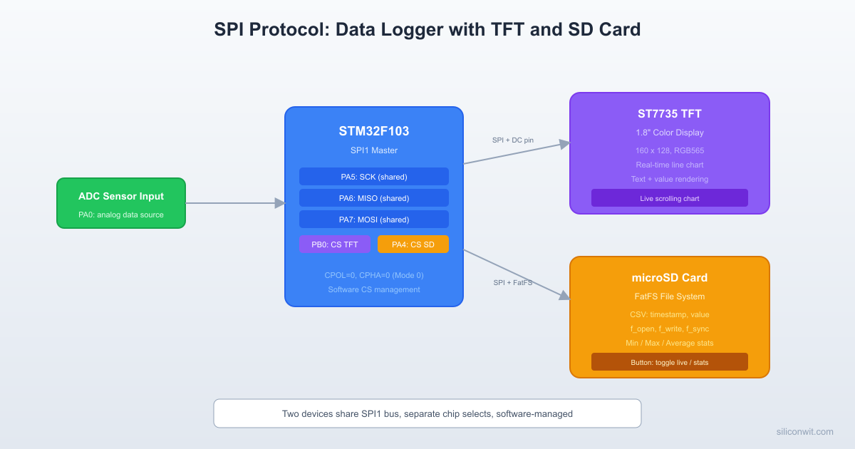
Both the ST7735 and SD cards use Mode 0 (CPOL=0, CPHA=0). When two devices share a bus but need different modes, you must reconfigure the SPI peripheral before switching. In our case both use Mode 0, so no reconfiguration is needed.
Multiple Devices on One Bus
MOSI, MISO, and SCK are shared between all devices. Each device gets its own CS pin, controlled by software. The protocol is simple: pull one CS low to talk to that device, keep all others high. Never have two CS lines low at the same time.
SPI Bus: Two Devices, Shared Lines
STM32 Blue Pill
┌──────────────┐
┌─────────┐ │ PA5 (SCK)────┼────┬───── SCK
│ ST7735 │ │ PA7 (MOSI)───┼────┼───── MOSI
│ TFT │<────┤ PA6 (MISO)───┼────┼───── MISO
│ Display │ CS │ PB0 (CS_TFT)─┼──┐ │
└─────────┘ │ │ │ │
│ │ │ │
┌─────────┐ │ │ │ │
│ microSD │<────┤ PA4 (CS_SD)──┼──┼─┘
│ Card │ CS │ │ │
│ Module │ │ │ │
└─────────┘ └──────────────┘ │
Only one CS low │
at a time! GND
Wiring
STM32 Pin
Function
ST7735 TFT
SD Card Module
PA5
SPI1_SCK
SCK
SCK
PA7
SPI1_MOSI
SDA (MOSI)
MOSI
PA6
SPI1_MISO
(not connected)
MISO
PB0
TFT_CS (GPIO)
CS
PB1
TFT_DC (GPIO)
DC
PB10
TFT_RST (GPIO)
RESET
PB12
SD_CS (GPIO)
CS
PA0
ADC1_IN0
PA1
Button input
PC13
Status LED
3.3V
Power
VCC
VCC
GND
Ground
GND
GND
The TFT backlight (LED pin) connects to 3.3V through a 100 ohm resistor, or directly to 3.3V if the module has an onboard resistor. Most modules do.
CubeMX Configuration
Create a new project for STM32F103C8Tx in STM32CubeIDE. Set the debug interface to Serial Wire (SYS category).
Configure SPI1. Mode: Full-Duplex Master. Parameter Settings: Prescaler = 4 (gives 18 MHz from 72 MHz APB2), Data Size = 8 Bits, First Bit = MSB, CPOL = Low, CPHA = 1 Edge, NSS = Software. The NSS software setting means we control chip select with GPIO.
Configure GPIO outputs. Set PB0 (TFT_CS), PB1 (TFT_DC), PB10 (TFT_RST), PB12 (SD_CS) as GPIO_Output, push-pull, no pull-up, high speed. Set initial output level to High for all CS pins.
Configure ADC1. Enable IN0 (PA0). Set resolution to 12-bit, right-aligned. Single conversion mode is fine; we trigger conversions manually.
Configure button input. Set PA1 as GPIO_Input with internal pull-up enabled.
Configure LED. Set PC13 as GPIO_Output (the onboard LED is active low on most Blue Pill boards).
Enable FatFS middleware. In the Middleware category, enable FATFS and select “User-defined” as the SD interface. This generates the FatFS source files and the diskio.c template where you implement the low-level SPI read/write functions.
Generate code and open main.c.
ST7735 TFT Display Driver
The ST7735 uses a command/data protocol layered on top of SPI. The DC (Data/Command) pin tells the display whether the byte being sent is a command or pixel data. DC low means command, DC high means data.
The ST7735 requires a specific startup sequence: hardware reset, software reset, exit sleep mode, set color format, then turn on the display.
main.c
voidtft_init(void) {
/* Hardware reset */
TFT_RST_LOW();
HAL_Delay(50);
TFT_RST_HIGH();
HAL_Delay(50);
tft_cmd(0x01); /* Software reset */
HAL_Delay(150);
tft_cmd(0x11); /* Sleep out */
HAL_Delay(150);
tft_cmd(0x3A); /* COLMOD: pixel format */
tft_data8(0x05); /* 16-bit RGB565 */
tft_cmd(0x36); /* MADCTL: memory access control */
tft_data8(0x00); /* Normal orientation: top-left origin */
tft_cmd(0xB1); /* Frame rate control (normal mode) */
tft_data8(0x01);
tft_data8(0x2C);
tft_data8(0x2D);
tft_cmd(0x29); /* Display ON */
HAL_Delay(100);
}
Drawing Functions
The ST7735 uses a window-based drawing model. You set a rectangular region (column start/end, row start/end), then stream pixel data into that window. Colors use RGB565 format: 5 bits red, 6 bits green, 5 bits blue, packed into 16 bits.
For a data logger, you need numbers on screen. A minimal 5x7 font stored as bitmaps handles digits, period, minus, and space. Each character is 5 columns of 7 pixels, stored as one byte per column (bit 0 = top row).
while (*str) { tft_draw_char(x, y, *str++, color, bg); x +=6; }
}
Drawing a Scrolling Line Chart
The chart occupies the lower portion of the display. New values enter from the right and old values scroll left. The draw function connects adjacent points with a simple vertical interpolation to produce smooth lines.
The SD card communicates over SPI using a command/response protocol. In SPI mode, the SD card uses only CS, SCK, MOSI (DI), and MISO (DO). CubeMX generates the FatFS middleware, but you must implement the low-level disk I/O functions in user_diskio.c (or diskio.c, depending on your CubeMX version).
SPI Speed Switching
SD cards require a slow clock (400 kHz or below) during initialization and can run faster afterward. We adjust the SPI prescaler dynamically:
/* 72 MHz / 16 = 4.5 MHz (safe for most SD cards) */
hspi1.Instance->CR1&=~SPI_CR1_SPE;
hspi1.Instance->CR1&=~SPI_CR1_BR;
hspi1.Instance->CR1|= SPI_BAUDRATEPRESCALER_16;
hspi1.Instance->CR1|= SPI_CR1_SPE;
}
staticvoidspi_set_display(void) {
/* 72 MHz / 4 = 18 MHz (fast for TFT) */
hspi1.Instance->CR1&=~SPI_CR1_SPE;
hspi1.Instance->CR1&=~SPI_CR1_BR;
hspi1.Instance->CR1|= SPI_BAUDRATEPRESCALER_4;
hspi1.Instance->CR1|= SPI_CR1_SPE;
}
Low-Level Disk I/O
The FatFS middleware calls functions in user_diskio.c to talk to the SD card. The key function is USER_initialize, which sends the SD card through its SPI-mode initialization sequence: 80 clock pulses with CS high, CMD0 to enter SPI mode, CMD8 to check the voltage range, then ACMD41 in a loop until the card is ready. After initialization, CMD58 reads the OCR register to determine if the card is standard capacity or SDHC.
The USER_read and USER_write functions follow the same pattern: select, send command (CMD17 for read, CMD24 for write), transfer the 512-byte data block, then deselect. CubeMX generates the function stubs; you fill in the SPI transfer calls.
FatFS File Operations
With the disk I/O layer in place, FatFS provides a familiar file API:
f_sync(&logfile); /* Flush to card after each write */
LED_OFF();
}
voidsd_close_log(void) {
f_close(&logfile);
}
Reading File Statistics
When the user presses the button to view statistics, the firmware reopens the CSV file, scans all records, and computes min, max, average, and sample count. The function opens the file read-only, skips the header line, then parses the ADC_Raw field from each row:
main.c
typedefstruct {
uint32_t count;
uint16_t min_val;
uint16_t max_val;
float avg_val;
} log_stats_t;
log_stats_tsd_read_stats(void) {
log_stats_t stats = {0, 4095, 0, 0.0f};
FIL rf;
spi_set_fast();
if (f_open(&rf, "LOG.CSV", FA_READ)!= FR_OK) return stats;
charbuf[80];
f_gets(buf, sizeof(buf), &rf); /* Skip header */
uint32_t sum =0;
while (f_gets(buf, sizeof(buf), &rf)) {
/* Skip to third field (ADC_Raw): Index,Time_ms,ADC_Raw,Voltage */
char*p = buf;
for (int f =0; f <2&& p; f++) { p =strchr(p, ','); if (p) p++; }
if (!p) continue;
uint16_t val = (uint16_t)atoi(p);
if (val <stats.min_val) stats.min_val= val;
if (val >stats.max_val) stats.max_val= val;
sum += val; stats.count++;
}
f_close(&rf);
if (stats.count>0) stats.avg_val= (float)sum /stats.count;
return stats;
}
Complete Main Loop
The main loop ties everything together: sample ADC, update display, log to SD, and handle the button press for view switching.
if (sd_ready) { sd_write_sample(sample_index++, now, adc_val); }
if (!view_mode) { spi_set_display(); show_live_view(adc_val); }
}
}
}
Project File Structure
DirectoryDataLogger_SPI/
DirectoryCore/
DirectoryInc/
main.h
fatfs.h
DirectorySrc/
main.c
user_diskio.c
DirectoryFATFS/
DirectoryTarget/
user_diskio.c
DirectoryApp/
fatfs.c
DirectoryDrivers/
DirectorySTM32F1xx_HAL_Driver/
…
DirectoryCMSIS/
…
DataLogger_SPI.ioc
Testing and Verification
Test the TFT display first. Comment out all SD card code. Flash the firmware and verify that the display initializes and shows the “SENSOR LOG” label with a voltage reading. Turn the potentiometer and confirm the chart scrolls.
Test the SD card separately. Comment out the TFT code. Mount the SD card, write a test file with f_puts, then remove the card and check the file on a PC. If mounting fails, check wiring (especially MISO), verify the card is formatted FAT32, and confirm the SPI prescaler is set to 256 during initialization.
Combine both devices. Enable all code. The key thing to verify is that chip select management works: the TFT does not glitch when the SD card is being accessed, and vice versa. Watch the status LED to confirm SD writes are happening.
Test view switching. Press the button to toggle to the statistics view. Confirm the sample count, min, max, and average values are reasonable. Switch back to live view and verify the chart resumes.
Production Notes
Level shifting. If your SD card module has a 5V level shifter (common on Arduino-targeted modules), the 3.3V signals from the Blue Pill may not reach the logic high threshold. Either use a 3.3V native module or bypass the level shifter.
Wear leveling. SD cards have internal wear leveling, but writing to the same file every 100 ms will eventually wear out the card. For long-term deployments, buffer multiple samples in RAM and write in larger blocks less frequently. Writing 512 bytes (one sector) at a time is most efficient.
Power consumption. The SD card draws 50 to 100 mA during writes. The TFT backlight draws another 20 to 40 mA. Make sure your 3.3V regulator can handle the combined load. The Blue Pill’s onboard regulator is rated for about 300 mA, which is adequate.
Decoupling. Add a 100 uF electrolytic capacitor across the SD card module power pins. SD cards create current spikes during sector writes that can momentarily drop the supply voltage and cause SPI errors.
Comments