Every digital system needs a clock. Your microcontroller’s CPU executes one instruction per clock cycle (or a few cycles, depending on the architecture). Communication peripherals like UART, SPI, and I2C derive their timing from the system clock. Even simple blinking LEDs need a timing reference. This lesson explores how oscillators generate periodic signals, from the humble 555 timer to the precision crystal oscillator on your MCU board. #AnalogElectronics #Oscillators #TimingCircuits
The 555 Timer IC
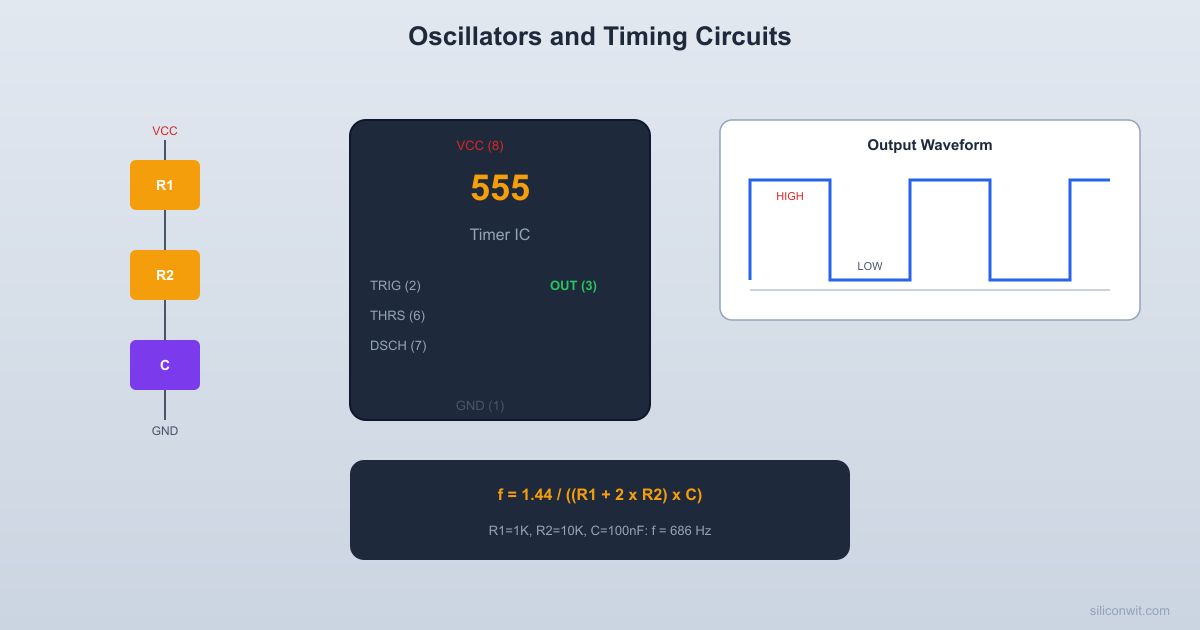
The 555 timer is one of the most versatile and widely used ICs in electronics. Introduced in 1972, billions have been manufactured. It can operate as an oscillator (astable mode), a one-shot timer (monostable mode), or a pulse-width modulator. Despite the availability of microcontrollers, the 555 remains useful for simple timing tasks that do not justify the complexity of a programmed solution.
555 Pinout
The 555 comes in an 8-pin DIP package (NE555, LM555) or a smaller CMOS version (LMC555, TLC555).
Pin
Name
Function
1
GND
Ground
2
TRIGGER
Starts timing when pulled below 1/3
3
OUTPUT
Timer output (HIGH or LOW)
4
RESET
Active LOW reset (connect to if unused)
5
CONTROL
Voltage control (bypass to GND with 10 nF if unused)
6
THRESHOLD
Ends timing when it rises above 2/3
7
DISCHARGE
Open collector output, discharges timing capacitor
8
VCC
Positive supply (4.5V to 16V for NE555)
How the 555 Works Internally
The 555 contains two comparators, an SR flip-flop, and a discharge transistor:
The upper comparator trips when the THRESHOLD pin (pin 6) exceeds 2/3
The lower comparator trips when the TRIGGER pin (pin 2) drops below 1/3
These comparators set and reset the flip-flop, which controls the output
The discharge transistor on pin 7 turns on when the output is LOW, providing a path to discharge the timing capacitor
This means the 555 oscillates between two voltage thresholds: 1/3 and 2/3 . The time it takes to charge and discharge between these thresholds (set by RC components) determines the frequency and duty cycle.
Astable Mode: Free-Running Oscillator
In astable mode, the 555 generates a continuous square wave without any external trigger. The output alternates between HIGH and LOW indefinitely.
Circuit
VCC (+5V)
|
+---[Ra] 1K---+---pin7 (DISCH)
| |
| [Rb] 68K
| |
+--pin8 (VCC) +---pin6 (THRESH)
| +---pin2 (TRIG)
+--pin4 (RST) |
| [C] 10nF
| |
| GND
|
+--10nF--pin5 (CTRL)--GND
|
+--pin3 (OUT)---> to buzzer/LED
|
pin1 (GND)
Timing Equations
HIGH time (output is HIGH while C charges through ):
LOW time (output is LOW while C discharges through only):
Frequency:
Duty cycle:
Notice that the duty cycle is always greater than 50% in the standard astable configuration because the charge path includes both and while the discharge path only uses . To get a 50% duty cycle, make much smaller than (but not zero, which would short to the discharge pin).
Worked Example: 1 kHz Buzzer
Target: with approximately 50% duty cycle.
Choose , , and :
That is higher than our target. Adjust: :
Close enough. The duty cycle:
Nearly 50% because is much smaller than .
Monostable Mode: One-Shot Timer
In monostable mode, the 555 produces a single output pulse of a defined duration when triggered. The output is normally LOW and goes HIGH for a precise time when the trigger pin is pulled below 1/3 .
Circuit
  VCC   |   +--[R] 100K--+--pin6 (THRESH)   |             +--pin7 (DISCH)   +--pin8       |   +--pin4     [C] 10uF   |             |   |            GND   +--10nF--pin5--GND   |   +--pin3 (OUT)---> LED + 220R   |  pin1 (GND)
  pin2 (TRIG) <--- button to GND  (10K pull-up to VCC)
  t_pulse = 1.1 x R x C = 1.1s
Timing Equation
The output goes HIGH for this duration after being triggered, then returns LOW.
Worked Example: 1 Second Pulse
Target:
Choose and :
Almost exactly 1 second. The actual pulse width depends on component tolerances (resistor and capacitor).
Monostable Applications
Debouncing: A button press triggers a clean, fixed-duration pulse regardless of switch bounce
Timeout generation: Generate a fixed delay after an event
Missing pulse detection: If the trigger does not arrive within the expected period, the output indicates a fault
Pulse stretching: Convert a very short pulse into a longer one that is easier to detect
Crystal Oscillators
While RC oscillators (like the 555) are useful for non-critical timing, they have limited accuracy. Component values drift with temperature, and manufacturing tolerances introduce frequency errors of 5 to 20%. When precise timing is needed, crystal oscillators provide stability of 10 to 50 ppm (parts per million).
How Crystal Oscillators Work
A quartz crystal is a piezoelectric material that vibrates at a very precise mechanical resonant frequency when an electric field is applied. This frequency depends on the crystal’s physical dimensions, which are cut with extreme precision during manufacturing.
The crystal acts as a very high-Q (quality factor) resonant circuit. The Q factor of a quartz crystal is typically 10,000 to 100,000, compared to about 10 to 100 for an LC circuit. This high Q means the oscillation frequency is extremely stable and resists being pulled off-frequency by circuit variations.
Common Crystal Frequencies
Frequency
Common Use
32.768 kHz
Real-time clock (RTC). Exactly Hz, divides evenly to 1 Hz.
4 MHz
General purpose, some AVR default
8 MHz
STM32 HSE (Blue Pill), AVR external clock
12 MHz
USB full-speed requirement
16 MHz
Arduino Uno (ATmega328P)
25 MHz
Ethernet PHY
Crystal Oscillator Circuit
A crystal typically connects between two pins of a microcontroller’s oscillator circuit, with two small load capacitors to ground:
┌--------┐
| MCU |
OSC_IN |---+ |
| | |
| XTAL 8MHz
| | |
OSC_OUT |---+ |
| |
└--------┘
OSC_IN--+--[XTAL]--+--OSC_OUT
| |
[CL1] 20pF [CL2] 20pF
| |
GND GND
The load capacitor values (typically 12 to 22 pF) are specified in the crystal datasheet. Using wrong values shifts the oscillation frequency slightly.
Internal RC Oscillators
Most modern microcontrollers include an internal RC oscillator (typically 8 to 16 MHz) that allows operation without an external crystal. The internal oscillator is less accurate (1 to 5% typical) but eliminates two external components and two PCB pads.
Oscillator Type
Accuracy
Cost
Components
Internal RC
1 to 5%
Free
None
External crystal
10 to 50 ppm
Low
Crystal + 2 capacitors
TCXO (temp compensated)
1 to 5 ppm
Moderate
Single package
OCXO (oven controlled)
0.01 ppm
High
Heated module
For UART communication, the baud rate tolerance is typically 3 to 5%. The internal RC oscillator (1%) is usually accurate enough. For USB, the specification requires 0.25% accuracy, which typically requires an external crystal or a specially trimmed internal oscillator.
RC Oscillator Circuits
Beyond the 555 timer, there are other RC oscillator topologies worth knowing.
Relaxation Oscillator
A relaxation oscillator uses a capacitor that charges to a threshold, then rapidly discharges and starts over. The 555 astable is a type of relaxation oscillator. You can also build one with a Schmitt trigger inverter (like the 74HC14):
┌────────────────┐
│ │
VCC ── R ──┬── Schmitt ───┤── Output
│ Inverter │
C │
│ │
GND │
┌── R_feedback─┘
The frequency depends on R, C, and the Schmitt trigger thresholds. This is even simpler than a 555 circuit.
Wien Bridge Oscillator
For generating clean sine waves (not square waves), the Wien bridge oscillator uses an op-amp with an RC feedback network. The frequency is:
This is the basis of many audio signal generators. We mention it here for completeness; building one is an advanced exercise that requires careful gain adjustment to prevent either signal decay or clipping.
Practical Build: 555 Astable Buzzer
Components Needed
Component
Quantity
Notes
Breadboard
1
From previous lessons
NE555 timer IC
1
DIP-8 package
Resistors: 1k, 10k, 47k, 68k, 100k ohm
1 each
1/4 watt
Capacitors: 10 nF, 100 nF ceramic
2 each
For timing and bypass
Electrolytic capacitor 10
1
For monostable experiment
Passive buzzer
1
Not active (active buzzers have built-in oscillator)
LED (red) + 220 ohm resistor
1 each
For visual indicator
Potentiometer 100k ohm
1
For variable frequency
Push button (momentary)
1
For monostable trigger
5V power source
1
USB or battery
Digital multimeter
1
Frequency mode if available
Jumper wires
Several
Male-to-male
Circuit: Astable Oscillator
Place the 555 on the breadboard
Orient the IC with the notch or dot at the top. Pin 1 (GND) is bottom-left, pin 8 (VCC) is top-left.
Connect power
Pin 8 to 5V, pin 1 to GND. Pin 4 (RESET) to 5V (disables reset). Place a 100 nF ceramic capacitor between pins 8 and 1 for decoupling.
Connect the bypass capacitor
Place a 10 nF ceramic capacitor from pin 5 (CONTROL) to GND. This stabilizes the internal voltage references.
Install timing components
Connect from pin 8 (VCC) to pin 7 (DISCHARGE). Connect from pin 7 to pin 6 (THRESHOLD). Jumper pin 6 to pin 2 (TRIGGER). Connect from pin 2/6 to GND.
Connect the buzzer
Connect the passive buzzer between pin 3 (OUTPUT) and GND. Add a 220 ohm resistor in series if the buzzer is very loud.
Apply power
You should hear a tone at approximately 1 kHz. If the buzzer is an active type (has a built-in oscillator), it will produce its own tone regardless of the 555 frequency. Make sure you are using a passive buzzer.
Measure the frequency
If your multimeter has a frequency mode, measure between pin 3 and GND. You should read approximately 1000 to 1100 Hz. If you have an oscilloscope, observe the square wave shape and duty cycle.
Change the frequency
Replace with a 100k potentiometer. Turning the potentiometer changes the frequency continuously. Calculate the frequency range: at minimum resistance (, which is dangerous; add a minimum 1k series resistor), . At maximum (100k), .
Add an LED indicator
Connect an LED with a 220 ohm resistor from pin 3 to GND. At frequencies below about 20 Hz, you can see the LED blinking. Above 20 Hz, it appears continuously lit (persistence of vision).
Experiment with low frequencies
Replace with and with . Now:
The LED blinks approximately once per second. You can time it with a stopwatch.
Optional: Monostable Mode
Reconfigure the circuit
Remove the connection between pins 6 and 2. Connect from VCC to pins 6 and 7. Connect from pin 6 to GND. Connect pin 2 to VCC through a 10k pull-up resistor.
Add a trigger button
Connect a push button from pin 2 to GND. When pressed, it pulls pin 2 below 1/3 VCC.
Connect the LED output
LED with 220 ohm from pin 3 to GND.
Calculate the pulse duration
Test
Press the button briefly. The LED lights for about 1.1 seconds and then turns off. Pressing the button again restarts the timing cycle.
Verification Checklist
Measurement
Expected Value
Your Measurement
Astable frequency (1k + 68k + 10nF)
~1050 Hz
________
Astable duty cycle
~50.4%
________
Low-frequency blink rate (1k + 68k + 10uF)
~1.05 Hz
________
Monostable pulse duration (100k + 10uF)
~1.1 seconds
________
Supply current (astable, no load)
~3 to 10 mA
________
Common Mistakes
Watch Out For These
Using an active buzzer with the 555: An active buzzer has its own internal oscillator and produces a fixed tone regardless of the input frequency. It works as a simple on/off indicator but defeats the purpose of the 555 oscillator. Use a passive buzzer to hear frequency changes.
Forgetting the 10 nF bypass on pin 5: Without this capacitor, the internal voltage references are susceptible to noise, causing frequency jitter and unstable operation.
Pin 4 (RESET) floating: If pin 4 is not connected, it may pick up noise and randomly reset the timer. Always tie it to VCC when not using the reset function.
Short-circuiting pin 7: If (pin 7 connected directly to VCC), the discharge transistor shorts to ground when it turns on, causing excessive current and potential damage to the 555. Always use a minimum of 1k for .
Confusing passive and active buzzers: They look identical. Check the marking or test with a DC voltage: an active buzzer sounds with just DC applied; a passive buzzer needs an AC signal.
How This Connects to Embedded Systems
Clocks Drive Everything Digital
MCU system clock: The crystal oscillator (or internal RC oscillator) on your MCU board sets the CPU clock speed. The STM32F103 Blue Pill uses an 8 MHz HSE crystal, multiplied by the PLL to 72 MHz. The ATmega328P on the Arduino Uno uses a 16 MHz crystal. Understanding oscillator stability helps you troubleshoot baud rate errors and timing drift.
UART baud rate: UART communication requires both sides to agree on the baud rate within about 3%. If your clock is off by more than that (due to an inaccurate internal oscillator or wrong PLL configuration), serial communication fails with garbled data.
PWM and timer frequencies: MCU timers divide the system clock to generate PWM signals, measure pulse widths, and create time delays. Knowing how RC timing works helps you understand what the timer prescaler and auto-reload registers do.
Real-time clocks: The 32.768 kHz crystal on many MCU boards drives the RTC (real-time clock) peripheral. Its frequency is chosen because , which divides perfectly down to 1 Hz using a simple binary counter.
555 timer vs MCU timer: For one-off timing tasks (power-on delay, simple oscillator), a 555 is simpler and more reliable than spinning up a full MCU. In production designs, the MCU’s built-in timers replace the 555 since you already have the MCU for other purposes.
Watchdog timers: The watchdog timer on an MCU uses an independent RC oscillator to detect if the main code has hung. Understanding RC oscillator drift helps you set appropriate watchdog timeout values.
Summary
Concept
Key Equation
Remember
555 astable frequency
Duty cycle always >50% in standard config
555 astable HIGH time
Charges through
555 astable LOW time
Discharges through only
555 monostable pulse
Single pulse, then returns LOW
Crystal accuracy
10 to 50 ppm
Much better than RC (1 to 5%)
32.768 kHz crystal
Hz
Divides evenly to 1 Hz for RTC
Next lesson: sensors and signal conditioning. We will combine voltage dividers, op-amps, and filters into complete measurement circuits that prepare real-world sensor signals for your MCU’s ADC.
Comments