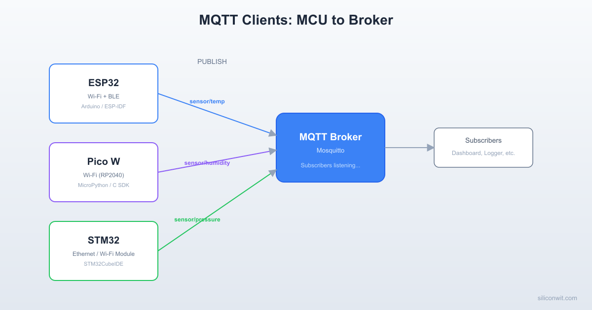
A broker sitting idle is not very useful. The real work begins when embedded devices connect, authenticate, publish sensor data on well-structured topics, and recover gracefully from disconnections. In this lesson you will write MQTT client firmware for three different MCU platforms (ESP32, RPi Pico W, and STM32 with an ESP-01 Wi-Fi module), all publishing to the same Mosquitto broker you configured in Lesson 2. By the end, you will have a three-node sensor network with a consistent topic hierarchy, structured JSON payloads, and robust reconnection logic. #MQTT #ESP32 #MultiPlatform
  MQTT Topic Hierarchy Design  ──────────────────────────────────────────  site/  └── building_a/      ├── esp32/      │   └── sensor_01/      │       ├── temperature    ◄── 23.5      │       ├── humidity       ◄── 65.2      │       └── status         ◄── online      ├── pico/      │   └── sensor_02/      │       ├── temperature      │       └── humidity      └── stm32/          └── sensor_03/              ├── temperature              └── air_quality
  Subscribe: site/building_a/+/+/temperature  Gets temperature from ALL devices.
What We Are Building
Three-MCU Sensor Network
Three microcontroller nodes, each reading a BME280 temperature/humidity sensor and publishing structured JSON to a shared MQTT broker. All nodes use the same topic hierarchy, the same payload format, and the same QoS strategy. You can monitor all three from a single mosquitto_sub session or from the SiliconWit.io dashboard.
Project specifications:
Parameter
Value
Platforms
ESP32 DevKitC, RPi Pico W, STM32F4 + ESP-01
Sensor
BME280 (I2C) on each platform
Broker (self-hosted)
Mosquitto on port 1883 (plain) or 8883 (TLS)
SiliconWit.io MQTT endpoint
mqtt.siliconwit.io:8883 (TLS, device token auth)
Topic pattern
site/building/device_type/device_id/measurement
Payload format
JSON with device_id, timestamp, temperature, humidity
QoS strategy
QoS 0 for telemetry, QoS 1 for alerts, QoS 2 for commands
Publish interval
Every 10 seconds
Reconnection
Exponential backoff with jitter, 60s max interval
Offline buffering
Store readings in flash/EEPROM, publish on reconnect
A flat topic like sensor/data works for one device. It falls apart at ten devices and becomes unmanageable at a hundred. A well-designed hierarchy lets you filter, route, and control access at every level.
The Hierarchy Pattern
The pattern used throughout this course follows a five-level structure:
site/building/device_type/device_id/measurement
For a concrete deployment:
factory/warehouse-a/esp32/esp32-001/telemetry
factory/warehouse-a/esp32/esp32-001/alerts
factory/warehouse-a/esp32/esp32-001/commands
factory/warehouse-a/pico/pico-001/telemetry
factory/warehouse-a/stm32/stm32-001/telemetry
factory/office/esp32/esp32-002/telemetry
Why Hierarchy Matters
ACLs (Access Control Lists). With Mosquitto ACLs from Lesson 2, you can restrict each device to only its own subtree. Device esp32-001 can publish to factory/warehouse-a/esp32/esp32-001/# but nowhere else. A dashboard user can subscribe to factory/warehouse-a/# to see all warehouse sensors without accessing the office.
Wildcards. MQTT provides two wildcard characters for subscriptions:
Wildcard
Meaning
Example
Matches
+
Single level
factory/+/esp32/+/telemetry
All ESP32 telemetry in all buildings
#
Multi-level (must be last)
factory/warehouse-a/#
Everything in warehouse-a
Dashboard subscriptions. A Grafana panel can subscribe to factory/+/+/+/telemetry and receive telemetry from every device across every building, regardless of device type. A building-specific panel subscribes to factory/warehouse-a/+/+/telemetry.
SiliconWit.io Topic Mapping
When connecting to the SiliconWit.io platform, the topic structure is different. SiliconWit.io uses a device-centric pattern:
d/{device_id}/t
Where {device_id} is the device identifier from your SiliconWit.io dashboard, and t is the telemetry subtopic. You authenticate with a device access token rather than username/password. We will show both self-hosted and SiliconWit.io connection examples for each platform.
JSON Payload Standard
Every device in this course publishes data in a consistent JSON format. This simplifies parsing, storage, and dashboard configuration because every consumer knows exactly what fields to expect.
Telemetry Payload
telemetry_payload.json
{
"device_id": "esp32-001",
"ts": 1710028800,
"temperature": 25.3,
"humidity": 60.1
}
Field
Type
Description
device_id
string
Unique identifier matching the topic hierarchy
ts
integer
Unix epoch timestamp (seconds since 1970-01-01)
temperature
float
Temperature in degrees Celsius
humidity
float
Relative humidity percentage
Alert Payload
alert_payload.json
{
"device_id": "esp32-001",
"ts": 1710028800,
"alert": "temperature_high",
"value": 45.2,
"threshold": 40.0
}
Command Payload
command_payload.json
{
"command": "set_interval",
"value": 30
}
Commands are published by the operator (or an automation rule) and received by the device on its commands subtopic. The device parses the JSON, applies the setting, and optionally publishes an acknowledgment.
Why JSON and Not Binary?
JSON adds overhead (field names are repeated in every message), but for most IoT applications publishing every 10 seconds or slower, the extra bytes are negligible compared to the TCP/TLS overhead. JSON is human-readable, easy to parse on every platform, and directly ingestible by InfluxDB, Grafana, and Node-RED. For high-frequency data (hundreds of messages per second), consider CBOR or Protocol Buffers, but that is beyond the scope of this lesson.
QoS Selection Strategy
Not every message deserves the same delivery guarantee. MQTT provides three QoS levels, and choosing the right one per message type balances reliability against bandwidth and latency.
QoS
Guarantee
Use In This Course
0
At most once (fire and forget)
Periodic telemetry (temperature, humidity every 10s). Missing one reading is acceptable because the next arrives in 10 seconds.
1
At least once (acknowledged)
Alert messages (threshold exceeded). You want confirmation that the broker received the alert. Duplicate delivery is tolerable.
2
Exactly once (four-step handshake)
Remote commands (change interval, reboot device). A duplicate command could cause unintended behavior, so exactly-once matters.
ESP32 MQTT Client
The ESP32 has native Wi-Fi, making it the most straightforward platform for MQTT. We use the ESP-IDF mqtt_client component, which supports TLS, automatic reconnection, and all three QoS levels.
The RPi Pico W has onboard Wi-Fi and runs MicroPython, which provides a very different development experience from the C-based ESP32. The umqtt.simple library handles MQTT, and the code is shorter but follows the same architecture: connect, publish, subscribe, reconnect.
The STM32F4 does not have built-in Wi-Fi, so we use an ESP-01 module connected over UART. The ESP-01 runs stock AT firmware and handles the entire TCP/Wi-Fi stack. The STM32 sends AT commands to connect to Wi-Fi, establish a TCP connection to the MQTT broker, and then sends raw MQTT packets over the TCP link.
This approach is common in industrial IoT where the main MCU handles real-time control and a secondary module handles connectivity.
Hardware Connections
STM32 Pin
ESP-01 Pin
Notes
PA2 (USART2 TX)
RX
3.3V logic, no level shifter needed
PA3 (USART2 RX)
TX
3.3V logic
3.3V
VCC, CH_PD
ESP-01 needs 3.3V (not 5V)
GND
GND
Common ground
AT Command Sequence
The ESP-01 AT firmware accepts commands over UART. Here is the complete sequence to connect to Wi-Fi and establish an MQTT connection:
printf("Received %u bytes from broker\r\n", rx_len);
/* In production, parse the MQTT packet header and extract payload */
}
}
/* Reconnect if disconnected */
if (!mqtt_connected) {
mqtt_reconnect();
}
}
}
Alternative: STM32 with Ethernet (lwIP + MQTT)
If your STM32 board has an Ethernet PHY (such as the STM32F407 Discovery with a LAN8720 module), you can use the lwIP TCP/IP stack with an MQTT client library directly, eliminating the ESP-01 entirely:
Network connections fail. Wi-Fi access points reboot, brokers restart for updates, and cellular modems lose signal. A production MQTT client must handle disconnections without losing data or flooding the network with reconnection attempts.
Exponential Backoff with Jitter
All three platform implementations in this lesson use the same reconnection strategy:
Start with a small delay. The first reconnection attempt waits 1 second. This handles brief network glitches quickly.
Double the delay on each failure. If the first attempt fails, wait 2 seconds. Then 4, 8, 16, 32 seconds. This prevents a flood of reconnection attempts when the broker is down for maintenance.
Cap the maximum delay. The backoff stops growing at 60 seconds. Without a cap, the delay would grow to hours after enough failures.
Add random jitter. Each delay gets a random offset of 0 to 25% of the backoff value. Jitter prevents the “thundering herd” problem where many devices reconnect at the exact same instant after a broker restart, potentially crashing it again.
/* In mqtt_event_handler, MQTT_EVENT_DISCONNECTED case */
int jitter = (esp_random() % (backoff_ms /4+1));
int delay = backoff_ms + jitter;
vTaskDelay(pdMS_TO_TICKS(delay));
backoff_ms = (int)(backoff_ms *2.0);
if (backoff_ms >60000) backoff_ms =60000;
The ESP-IDF MQTT client has built-in reconnection, but implementing your own gives you control over the backoff parameters and allows you to trigger offline buffering during the wait.
The STM32 uses HAL_GetTick() as a pseudo-random source since it does not have a hardware RNG on all variants. For STM32F4 and above, you can use the hardware RNG peripheral (HAL_RNG_GenerateRandomNumber) for better jitter.
Message Buffering When Offline
When the MQTT connection drops, you have two choices: discard the readings or buffer them for later. For most IoT applications, buffering is worth the extra complexity because gaps in time-series data make trends and anomalies harder to detect.
Buffer Architecture
The buffer stores readings in a circular array. When the array is full, the oldest entry is overwritten. On reconnect, the buffer is flushed in chronological order before new readings are published.
For power-cycle persistence on STM32, write the buffer to internal flash or an external EEPROM (AT24C256 over I2C). Internal flash writes require erasing a full sector first, so batch the writes and use a wear-leveling strategy if the device cycles power frequently.
Testing the Three-Node Network
With all three clients implemented, it is time to verify that they all publish to the same broker and that the data is consistent.
Start the Broker
Make sure your Mosquitto broker from Lesson 2 is running:
Terminal 1: Start Mosquitto
sudosystemctlstartmosquitto
sudosystemctlstatusmosquitto
Subscribe to All Telemetry
Open a terminal and subscribe to all telemetry topics using the multi-level wildcard:
Terminal 2: Subscribe to all telemetry
mosquitto_sub-hlocalhost-p1883\
-u"dashboard-user"-P"dashboard-password"\
-t"factory/warehouse-a/+/+/telemetry"-v
The -v flag prints the topic alongside the payload, so you can see which device sent each message.
Flash and Run All Three Nodes
ESP32. Build and flash the ESP-IDF project, then open the serial monitor.
Terminal window
cdesp32_mqtt_client
idf.pybuildflashmonitor
RPi Pico W. Copy the Python files to the Pico via Thonny or mpremote.
Unplug the Wi-Fi router (or disable the Wi-Fi access point) for 30 seconds. Watch the serial monitors on each device. You should see backoff messages with increasing delays.
Restore Wi-Fi. Each device should reconnect automatically. The ESP32 and Pico should flush their buffered readings, and you will see a burst of messages in mosquitto_sub with timestamps from the offline period.
Stop and restart Mosquitto. Run sudo systemctl stop mosquitto, wait 20 seconds, then sudo systemctl start mosquitto. The LWT message should appear for each device (status: offline), and then the devices should reconnect and publish their online status.
Send a command. Publish a command to change the publish interval:
Terminal window
mosquitto_pub-hlocalhost-p1883\
-u"admin"-P"admin-password"\
-t"factory/warehouse-a/esp32/esp32-001/commands"\
-m'{"command":"set_interval","value":30}'
The ESP32 serial monitor should show that it received the command and changed its interval to 30 seconds.
Testing with SiliconWit.io
To verify the SiliconWit.io connection:
Log in to siliconwit.io and create a device. Copy the device ID and access token.
Update the firmware configuration on one of the MCUs to use the SiliconWit.io connection settings.
Flash and run. The device should connect to mqtt.siliconwit.io:8883 and publish to the d/{device_id}/t topic.
Check the SiliconWit.io dashboard. Your telemetry data should appear on the device’s data page within a few seconds.
Summary
This lesson built MQTT client firmware for three different MCU platforms, all publishing to a single broker with a consistent topic hierarchy and JSON payload format.
Topic Hierarchy
The five-level site/building/device_type/device_id/measurement pattern enables fine-grained ACLs, flexible wildcard subscriptions, and clean dashboard layouts. SiliconWit.io uses d/{device_id}/t for its managed topics.
Three Platforms
ESP32 (ESP-IDF with native Wi-Fi), RPi Pico W (MicroPython with umqtt.simple), and STM32 (AT commands to ESP-01 or lwIP with Ethernet). Each speaks the same MQTT and JSON, so the broker and dashboards do not care which MCU sent the data.
Resilient Connections
Exponential backoff with jitter prevents thundering herd reconnections. Message buffering in flash/EEPROM preserves data during outages. LWT messages notify subscribers when a device goes offline.
QoS Strategy
QoS 0 for frequent telemetry (acceptable loss), QoS 1 for alerts (at least once), QoS 2 for commands (exactly once). Choosing the right QoS per message type balances reliability against bandwidth.
In the next lesson, you will connect this three-node network to InfluxDB and Grafana to build real-time dashboards that visualize the data from all three devices on a single screen.
Exercises
Exercise 1: Add a Third Sensor Type. Connect a light sensor (BH1750 or LDR with ADC) to one of the MCUs. Extend the JSON payload to include a "light_lux" field. Update the topic hierarchy to include the new measurement type. Verify that the new field appears in mosquitto_sub output.
Exercise 2: Implement Command Acknowledgment. When a device receives a command (such as set_interval), it should publish an acknowledgment message on a new ack subtopic (for example, factory/warehouse-a/esp32/esp32-001/ack). The acknowledgment payload should include the command name, the new value, and a success/failure status. Implement this on all three platforms.
Exercise 3: Stress Test Offline Buffering. Disconnect the Wi-Fi for 5 minutes while all three devices are running with a 10-second publish interval. That produces approximately 30 buffered readings per device. Reconnect and measure how long it takes to flush all buffered messages. Experiment with different flush delays (10 ms, 50 ms, 200 ms) and observe whether the broker drops any messages.
Exercise 4: Dual-Destination Forwarding. Modify one of the clients (your choice of platform) to connect to both your self-hosted Mosquitto broker and SiliconWit.io’s MQTT endpoint simultaneously. Publish the same telemetry to both destinations. This requires maintaining two MQTT client instances and handling reconnection for each independently. Document the additional RAM and CPU usage compared to a single-destination configuration.
Comments