Most microcontrollers have fixed pin assignments, but the ESP32’s GPIO matrix lets you route almost any peripheral signal to almost any pin. In this lesson you will explore that flexibility along with the LEDC PWM engine, pulse counter, and RMT driver. The project is a lamp dimmer that requires no external buttons: just touch the bare wire connected to a touch-capable GPIO and the LED smoothly fades up or down. #ESP32 #GPIO #TouchSensor
What We Are Building
Capacitive Touch Lamp Dimmer
A lamp dimmer with no mechanical switches. The ESP32’s built-in capacitive touch sensor detects your finger on a bare wire or copper pad. A short touch toggles the lamp on and off; a long press smoothly ramps brightness up or down using the LEDC PWM peripheral. The firmware debounces touch events and stores the last brightness level in NVS flash.
Project specifications:
Parameter
Value
MCU
ESP32 DevKitC
Touch Input
Touch0 (GPIO4), bare wire or copper tape
LED Output
High-brightness white LED on LEDC channel 0
PWM Resolution
13-bit (8192 steps), 5 kHz frequency
Touch Threshold
Calibrated at boot, adaptive filtering
Short Touch
Toggle on/off
Long Touch (hold)
Ramp brightness up/down
Brightness Persistence
Last level saved to NVS flash
Current-Limiting Resistor
100 ohm (for high-brightness LED)
Bill of Materials
Ref
Component
Quantity
Notes
U1
ESP32 DevKitC
1
Same board from Lesson 1
D1
High-brightness white LED (or small LED strip)
1
20mA for single LED, MOSFET for strip
R1
100 ohm resistor
1
Adjust for your LED
Bare wire or copper tape
1 piece
Touch pad (connect to GPIO4)
Breadboard + jumper wires
1 set
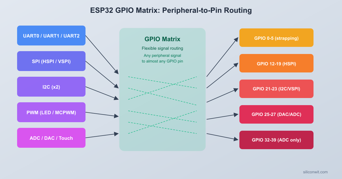
The ESP32 GPIO Matrix
Most microcontrollers wire each peripheral to a fixed set of pins. The ESP32 takes a different approach: a programmable routing fabric called the GPIO matrix sits between the internal peripheral signals and the physical pins. You can connect almost any peripheral output to almost any GPIO, and route almost any GPIO to almost any peripheral input. This is why you see ESP32 projects assigning SPI, I2C, UART, and PWM to seemingly arbitrary pins.
How Signal Routing Works
ESP32 GPIO Matrix Signal Routing
┌──────────┐ ┌──────────────┐ ┌──────────┐
│Peripheral│ │ GPIO Matrix │ │ Physical │
│ Signals │ │ │ │ Pads │
│ │ │ ┌──────────┐ │ │ │
│ LEDC Ch0 ├───>│ │ Output │ ├───>│ GPIO 18 │
│ SPI MOSI ├───>│ │ Matrix │ ├───>│ GPIO 23 │
│ UART TX ├───>│ └──────────┘ │ │ │
│ │ │ ┌──────────┐ │ │ │
│ UART RX │<───┤ │ Input │ │<───┤ GPIO 16 │
│ PCNT Sig │<───┤ │ Matrix │ │<───┤ GPIO 25 │
│ │ │ └──────────┘ │ │ │
└──────────┘ └──────────────┘ └──────────┘
~25 ns delay per routing stage
The GPIO matrix maintains two routing tables. The output matrix maps peripheral signals to GPIO pads, and the input matrix maps GPIO pads to peripheral inputs. When you configure LEDC channel 0 to output on GPIO18, the GPIO matrix programs one entry in the output table: “peripheral signal X goes to pad 18.” When you configure UART RX on GPIO16, the input table gets an entry: “pad 16 feeds into UART RX.”
Some signals bypass the matrix entirely for better timing. These are called “direct I/O” or “dedicated GPIO” connections. The SPI flash interface, JTAG pins, and the high-speed SD card interface use direct connections because the matrix adds about 25 ns of propagation delay per stage. For LEDC PWM, touch sensing, and general-purpose I/O, the matrix delay is negligible.
GPIO Configuration with gpio_config()
The ESP-IDF provides gpio_config() as the primary way to set up GPIO pins. You fill a gpio_config_t structure describing the direction, pull resistors, and interrupt behavior, then pass it in:
.intr_type = GPIO_INTR_DISABLE, /* No interrupt */
};
gpio_config(&io_conf);
The pin_bit_mask field is a 64-bit mask, so you can configure multiple pins in one call by OR-ing their bit positions together. For input pins, set .mode = GPIO_MODE_INPUT and enable a pull-up or pull-down as needed.
Pin Limitations
Not every GPIO is fully flexible. Keep these restrictions in mind:
GPIO Range
Limitation
GPIO 34, 35, 36, 39
Input only. No internal pull-up or pull-down. Cannot drive outputs.
GPIO 0
Strapping pin. Directly affects boot mode. Pulled high internally. Avoid using for general I/O unless you understand the boot sequence.
GPIO 2
Strapping pin. Must be low or floating during boot for flash download mode.
GPIO 12
Strapping pin. Sets flash voltage at boot (low = 3.3V, high = 1.8V). Pulling high can prevent boot on some modules.
GPIO 15
Strapping pin. Controls UART0 debug output at boot.
GPIO 6, 7, 8, 9, 10, 11
Connected to the internal SPI flash. Do not use on modules with a single flash chip (WROOM-32).
For this project, we use GPIO18 for the LED output and GPIO4 for the touch input. Both are safe, general-purpose pins with no strapping restrictions.
LEDC PWM Controller
You used LEDC in Lesson 1 at 8-bit resolution. Now we configure it at 13-bit resolution (8192 steps) and 5 kHz, which gives much smoother dimming, especially at low brightness levels where the human eye is most sensitive to step changes.
Timer Groups
The LEDC peripheral has two groups of timers:
Group
Timers
Channels
Clock Source
High-speed
Timer 0, 1, 2, 3
Channel 0 through 7
80 MHz APB clock or REF_TICK
Low-speed
Timer 0, 1, 2, 3
Channel 0 through 7
80 MHz APB clock or REF_TICK or slow clock
In ESP-IDF v5.x, most applications use LEDC_LOW_SPEED_MODE because the high-speed mode is not available on some ESP32 variants (ESP32-S2, ESP32-C3). Low-speed mode is portable across the entire ESP32 family. The functional difference is minimal for LED dimming.
Configuration
#include"driver/ledc.h"
#defineLEDC_TIMER LEDC_TIMER_0
#defineLEDC_MODE LEDC_LOW_SPEED_MODE
#defineLEDC_CHANNEL LEDC_CHANNEL_0
#defineLEDC_GPIO18
#defineLEDC_FREQUENCY5000 /* 5 kHz */
#defineLEDC_RESOLUTION LEDC_TIMER_13_BIT /* 0-8191 duty range */
voidledc_pwm_init(void)
{
ledc_timer_config_t timer_conf = {
.speed_mode = LEDC_MODE,
.duty_resolution = LEDC_RESOLUTION,
.timer_num = LEDC_TIMER,
.freq_hz = LEDC_FREQUENCY,
.clk_cfg = LEDC_AUTO_CLK,
};
ledc_timer_config(&timer_conf);
ledc_channel_config_t ch_conf = {
.speed_mode = LEDC_MODE,
.channel = LEDC_CHANNEL,
.timer_sel = LEDC_TIMER,
.intr_type = LEDC_INTR_DISABLE,
.gpio_num = LEDC_GPIO,
.duty =0,
.hpoint =0,
};
ledc_channel_config(&ch_conf);
/* Install the fade service (needed for hardware fade functions) */
ledc_fade_func_install(0);
}
The ledc_fade_func_install(0) call registers an ISR handler that the LEDC fade engine uses to signal completion. Pass 0 for the interrupt allocation flags (default priority). You must call this once before using any fade functions.
Hardware Fade Functions
Instead of manually stepping the duty cycle in a loop (which wastes CPU time), the LEDC peripheral has a built-in fade engine that ramps between two duty values over a specified time. The CPU starts the fade and the hardware handles the rest:
/* Fade from current duty to target_duty over 1000 ms */
The LEDC_FADE_NO_WAIT flag returns immediately so your task can do other work while the fade runs. Use LEDC_FADE_WAIT_DONE if you need to block until the fade completes.
There is also ledc_set_fade_with_step() for finer control over step size and interval. For our lamp dimmer, ledc_set_fade_with_time() is simpler and works well.
Why Hardware PWM Beats Software PWM
Software PWM toggles a GPIO pin in a timer ISR or a tight loop. On a single-core MCU running a busy RTOS, ISR jitter causes visible flicker. The LEDC peripheral generates the PWM waveform in dedicated hardware with zero CPU involvement after setup. It also survives light-sleep mode (in low-speed mode with the slow clock), which software PWM cannot.
Capacitive Touch Sensor
The ESP32 has a built-in capacitive touch controller that works with bare copper pads, wires, or PCB traces. No external components are needed. When you touch the pad, your body’s capacitance changes the charge/discharge timing on the pin, and the touch controller measures that change.
Touch-Capable GPIOs
Ten GPIOs support capacitive touch sensing:
Touch Channel
GPIO
Touch0
GPIO 4
Touch1
GPIO 0 (strapping pin, use with care)
Touch2
GPIO 2 (strapping pin, use with care)
Touch3
GPIO 15
Touch4
GPIO 13
Touch5
GPIO 12 (strapping pin, use with care)
Touch6
GPIO 14
Touch7
GPIO 27
Touch8
GPIO 33
Touch9
GPIO 32
For this project we use Touch0 on GPIO4, which has no strapping conflicts.
How Capacitive Sensing Works
Capacitive Touch Sensing
┌──────────────────────────────────┐
│ No Touch With Touch │
│ │
│ GPIO4 ─┐ GPIO4 ─┐ │
│ ─┤─ Wire ─┤─ │
│ │ │ │
│ Low C │ High C│ │
│ │ ┌────┤ │
│ │ │Finger │
│ │ └────┘ │
│ │
│ Fast cycling Slow cycling │
│ High count Low count │
│ = not touched = touched │
└──────────────────────────────────┘
The touch controller charges each touch pad to a reference voltage, then counts how many charge/discharge cycles occur within a fixed measurement window. When nothing is touching the pad, the count is high (low capacitance, fast cycling). When your finger approaches, the added capacitance slows down the cycling and the count drops. The raw reading from touch_pad_read() reflects this count: lower values mean a touch is detected.
ESP-IDF Touch API
The ESP-IDF v5.x touch driver API for the original ESP32 uses the driver/touch_pad.h header. (Note: ESP32-S2 and ESP32-S3 have a redesigned touch controller with a different API. The code in this lesson targets the original ESP32.)
#include"driver/touch_pad.h"
voidtouch_init(void)
{
/* Initialize the touch pad driver */
touch_pad_init();
/* Set the reference voltage for charging and discharging */
/* Enable the built-in hardware filter for noise reduction.
The filter period is in ms. A value of 10 works well. */
touch_pad_filter_start(10);
}
The second argument to touch_pad_config() is a threshold value. We pass 0 here because we will calibrate the threshold at boot time rather than guessing a fixed number.
Calibration at Boot
Touch readings vary depending on the physical pad geometry, wire length, humidity, and even the PCB layout. Hard-coding a threshold is fragile. A better approach is to read the baseline value at boot (when no one is touching the pad) and set the threshold as a percentage of that baseline:
#defineTOUCH_THRESH_PERCENT80 /* Touch triggers at 80% of baseline */
Call touch_calibrate() after touch_init() and a brief settling delay (about 200 ms is enough for the filter to stabilize). If the threshold value is too sensitive (phantom touches), lower the percentage to 70%. If it is not sensitive enough, raise it to 85%.
Filtering and Debouncing
The hardware filter (touch_pad_filter_start()) smooths out electrical noise. For reliable touch detection, you also need software debouncing. The simplest approach is to require the reading to stay below the threshold for several consecutive samples before declaring a touch, and to stay above the threshold for several consecutive samples before declaring a release:
#defineDEBOUNCE_COUNT3
staticboolis_touched(void)
{
staticint touch_count =0;
staticint release_count =0;
staticbool touched =false;
uint16_t val;
touch_pad_read_filtered(TOUCH_PAD_NUM0, &val);
if (val < touch_threshold) {
touch_count++;
release_count =0;
if (touch_count >= DEBOUNCE_COUNT &&!touched) {
touched =true;
}
} else {
release_count++;
touch_count =0;
if (release_count >= DEBOUNCE_COUNT && touched) {
touched =false;
}
}
return touched;
}
NVS (Non-Volatile Storage)
NVS is a key-value store built into ESP-IDF that persists data in flash across power cycles and firmware updates. It uses the NVS partition defined in the partition table (at offset 0x9000 by default). Unlike raw flash writes, NVS handles wear leveling, power-loss safety, and namespace isolation automatically.
Core API
#include"nvs_flash.h"
#include"nvs.h"
/* Initialize the default NVS partition (call once at startup) */
esp_err_t ret =nvs_flash_init();
if (ret == ESP_ERR_NVS_NO_FREE_PAGES ||
ret == ESP_ERR_NVS_NEW_VERSION_FOUND) {
/* NVS partition was corrupted or format changed. Erase and retry. */
brightness =0; /* Default if key does not exist */
}
/* Close the handle when done */
nvs_close(nvs);
The nvs_commit() call is important. Without it, writes stay in a RAM buffer and may be lost if power is cut. For our lamp dimmer, we commit after each brightness change.
NVS supports several value types: u8, i8, u16, i16, u32, i32, u64, i64, str (strings), and blob (binary data). Each key name can be up to 15 characters.
Storing Brightness Across Power Cycles
The lamp dimmer will save the current brightness to NVS whenever it changes. On boot, it reads the saved value and restores the LED to that level. If the key does not exist (first boot), it defaults to zero (off).
Circuit Connections
ESP32 DevKitC Touch Lamp Circuit
┌─────────────┐
│ GP18 ├──[R1 100R]──┤>├── GND
│ │ LED
│ GP4 ├──── Bare wire / copper pad
│ │ (touch sensor)
│ GND ├──── GND rail
│ │
│ USB │
└──────┤├─────┘
Connect the components on a breadboard as follows:
ESP32 Pin
Component
Notes
GPIO 18
LED anode through 100 ohm resistor
LEDC PWM output
GND
LED cathode
Common ground
GPIO 4
Bare wire or copper tape (touch pad)
Touch0 input
GND
Breadboard ground rail
Common ground
The touch pad is simply a bare wire (5 to 10 cm) or a piece of copper tape connected to GPIO4. No pull-up or pull-down resistor is needed; the touch controller handles biasing internally. Keep the wire away from other signals to reduce noise coupling.
For the LED, a 100 ohm resistor limits current to about 13 mA at 3.3V (accounting for the LED forward voltage drop of about 2V). This is within the ESP32 GPIO safe operating range. If you are driving an LED strip through a MOSFET, connect the MOSFET gate to GPIO18 through a 100 ohm gate resistor and drive the strip from 5V or 12V.
Complete Firmware
Here is the complete main.c for the capacitive touch lamp dimmer. The firmware initializes LEDC at 13-bit resolution, calibrates the touch sensor at boot, and runs a FreeRTOS task that distinguishes short touches (toggle on/off) from long presses (ramp brightness). Brightness is saved to NVS on every change.
#include<stdio.h>
#include<string.h>
#include"freertos/FreeRTOS.h"
#include"freertos/task.h"
#include"driver/ledc.h"
#include"driver/touch_pad.h"
#include"nvs_flash.h"
#include"nvs.h"
#include"esp_log.h"
staticconstchar*TAG ="touch_lamp";
/* ---------- Pin and PWM configuration ---------- */
1 /* Run on APP_CPU to avoid Wi-Fi/system task contention */
);
/* app_main returns; the touch task keeps running */
}
How the Code Works
The firmware has four main layers that cooperate through shared state:
NVS layer:nvs_init_storage() initializes the flash partition. nvs_load_brightness() and nvs_save_brightness() read and write a single uint16 value under the “lamp” namespace. If the key does not exist on first boot, the default is zero.
LEDC layer:ledc_pwm_init() configures Timer 0 at 13-bit resolution and 5 kHz, binds Channel 0 to GPIO18, and installs the fade service. Two helper functions provide immediate duty updates and timed fade transitions.
Touch layer:touch_init_sensor() sets up the touch pad hardware and starts the noise filter. touch_calibrate() reads the baseline after a settling period and computes the threshold at 80% of that value. touch_is_active() returns true when the filtered reading drops below the threshold.
Touch task: The main control loop runs every 20 ms. It debounces the raw touch signal, tracks how long the pad has been held, and decides between two behaviors:
Short touch (under 400 ms): Toggles the lamp on or off using the LEDC fade engine for a smooth transition. When turning on, it restores the last saved brightness.
Long press (400 ms or longer): Ramps brightness up or down in steps. The ramp direction reverses each time you release and touch again, and it also reverses when hitting the top or bottom of the range.
On every release, the current brightness is saved to NVS so it persists across power cycles.
CMakeLists.txt Files
Top-Level CMakeLists.txt
cmake_minimum_required(VERSION 3.16)
include($ENV{IDF_PATH}/tools/cmake/project.cmake)
project(touch-lamp-dimmer)
main/CMakeLists.txt
idf_component_register(SRCS "main.c"
INCLUDE_DIRS ".")
Building and Flashing
Create the project directory and add the files:
Terminal window
mkdir-ptouch-lamp-dimmer/main
# Place the top-level CMakeLists.txt in touch-lamp-dimmer/
# Place main/CMakeLists.txt and main/main.c in touch-lamp-dimmer/main/
Set the target chip:
Terminal window
cdtouch-lamp-dimmer
idf.pyset-targetesp32
Build the project:
Terminal window
idf.pybuild
Connect the ESP32 DevKitC via USB and flash:
Terminal window
idf.py-p/dev/ttyUSB0flashmonitor
On macOS use /dev/cu.usbserial-XXXX or /dev/cu.SLAB_USBtoUART. On Windows use COM3 or the appropriate port.
Watch the serial output for calibration values:
I (325) touch_lamp: Capacitive Touch Lamp Dimmer starting
I (527) touch_lamp: Touch calibration: baseline=523, threshold=418
I (528) touch_lamp: Touch task running on core 1
Test the touch sensor:
Short touch: Tap the bare wire briefly. The LED should toggle on/off with a smooth fade.
Long press: Hold the wire for more than half a second. The LED should ramp up or down.
Power cycle: Unplug the USB cable, plug it back in. The LED should restore the last brightness level.
Press Ctrl+] to exit the serial monitor.
Adjusting Touch Sensitivity
If you get phantom touches (the LED flickers without contact), try these fixes in order:
Lower TOUCH_THRESH_PERCENT from 80 to 70 or 65.
Increase DEBOUNCE_COUNT from 3 to 5.
Shorten the touch wire. Long wires pick up more noise.
Keep the wire away from the USB cable and power lines.
If the sensor does not respond to touch at all, check that the wire is connected to GPIO4 (not another pin), and verify in the serial output that the baseline reading is reasonable (typically 400 to 700 for a short wire). A baseline near zero indicates a wiring problem.
Pulse Counter and RMT Overview
The GPIO matrix routes signals not only to common peripherals like LEDC and UART, but also to two specialized peripherals worth knowing about: the Pulse Counter (PCNT) and the Remote Control Transceiver (RMT).
Pulse Counter (PCNT)
The PCNT peripheral counts edges on a signal pin and optionally uses a second pin as a direction control. It is designed for:
Rotary encoders: The two quadrature signals feed into the signal and control inputs. The counter increments on one rotation direction and decrements on the other, with no CPU involvement.
Frequency measurement: Count rising edges over a known time window to compute frequency.
The ESP32 has 8 PCNT units, each with a 16-bit signed counter and configurable high/low limit watchpoints that trigger interrupts. In ESP-IDF v5.x, the PCNT driver uses the driver/pulse_cnt.h API with a handle-based design:
#include"driver/pulse_cnt.h"
/* Create a PCNT unit */
pcnt_unit_config_t unit_config = {
.high_limit =100,
.low_limit =-100,
};
pcnt_unit_handle_t pcnt_unit =NULL;
pcnt_new_unit(&unit_config, &pcnt_unit);
/* Create a channel on that unit */
pcnt_chan_config_t chan_config = {
.edge_gpio_num = GPIO_NUM_25, /* Signal input */
.level_gpio_num = GPIO_NUM_26, /* Direction control (optional) */
You configure edge and level actions (count up, count down, hold) to define how the counter responds to each combination of signal edge and direction level.
RMT (Remote Control Transceiver)
The RMT peripheral was originally designed for infrared remote control protocols, but its ability to transmit and receive precisely timed pulse sequences makes it useful for several other applications:
WS2812 / NeoPixel LEDs: The RMT transmitter generates the exact 800 kHz timing that addressable LEDs require, without bit-banging or DMA tricks.
IR transmit and receive: Encode NEC, RC5, or custom IR protocols. The hardware captures pulse widths for decoding.
DHT sensors: The RMT receiver can capture the timing-sensitive one-wire protocol used by DHT11/DHT22 temperature sensors.
The ESP32 has 8 RMT channels (4 TX, 4 RX). In ESP-IDF v5.x, the RMT driver uses driver/rmt_tx.h and driver/rmt_rx.h with an encoder abstraction that converts your data into RMT symbols (pulse pairs with configurable duration and level):
#include"driver/rmt_tx.h"
rmt_tx_channel_config_t tx_config = {
.gpio_num = GPIO_NUM_18,
.clk_src = RMT_CLK_SRC_DEFAULT,
.resolution_hz =10000000, /* 10 MHz, 100 ns per tick */
.mem_block_symbols =64,
.trans_queue_depth =4,
};
rmt_channel_handle_t tx_chan =NULL;
rmt_new_tx_channel(&tx_config, &tx_chan);
Both PCNT and RMT will appear in later projects. The key takeaway for now is that the ESP32 offloads timing-critical tasks to dedicated hardware, freeing the CPU for application logic.
Exercises
Add a second touch pad for mode selection. Wire a second bare wire to GPIO27 (Touch7). Modify the firmware so that Touch0 still controls brightness, but a short touch on Touch7 cycles through three modes: solid on, slow pulse (brightness ramps up and down in a loop), and off. You will need a second set of debounce variables and a mode state machine.
Implement exponential dimming. Human brightness perception is logarithmic, so linear PWM steps look uneven (the low end changes too fast, the high end looks flat). Replace the linear ramp with a gamma-corrected curve. Create a lookup table of 256 entries where table[i] = (int)(pow(i / 255.0, 2.8) * 8191), and use it to map a linear 0 to 255 brightness value to a 13-bit duty cycle. Compare the visual smoothness with the original linear ramp.
Log touch events with timestamps. Add an esp_timer_get_time() call in the touch task and print a log line every time a touch or release is detected, including the raw filtered reading, the threshold, and the elapsed time since boot in milliseconds. Use this to measure the actual debounce latency and verify it matches your DEBOUNCE_COUNT * TOUCH_POLL_MS expectation.
Store and recall multiple brightness presets. Extend the NVS storage to save three preset brightness levels under keys “preset0”, “preset1”, “preset2”. A triple-tap (three short touches within 1 second) saves the current brightness to the next preset slot. A double-tap recalls the next stored preset. Display the active preset number in the serial log.
Summary
You explored the ESP32 GPIO matrix and how it routes peripheral signals to arbitrary pins. You configured LEDC PWM at 13-bit resolution with hardware fade support, set up the built-in capacitive touch sensor with boot-time calibration and debouncing, and used NVS to persist brightness across power cycles. The complete firmware distinguishes short touches (toggle) from long presses (ramp) and saves state to flash. You also saw how the Pulse Counter and RMT peripherals handle specialized timing tasks in hardware, freeing the CPU for application logic.
Comments