Load sharing by stiffness
Watch how the total load splits between two parallel members: the stiffer one (higher E times A divided by L) always takes the larger share, even when the other member has a bigger cross-section.
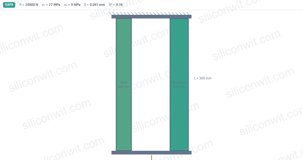
In a compound bar the load does not split equally by area: the stiffer material quietly takes the larger share, and the softer one carries far less than its cross-section might suggest. Textbook exercises hide this because the numbers work out neatly on paper. In practice, one member can be operating close to its yield stress while the other is barely loaded, and the difference is invisible until you run the numbers member by member. This simulator puts both members on screen, ramps the total load, and shows the force, stress, and elongation in each one as they evolve together. #AxialLoading #CompoundBars #SolidMechanics
Open SimulatorLoad sharing by stiffness
Watch how the total load splits between two parallel members: the stiffer one (higher E times A divided by L) always takes the larger share, even when the other member has a bigger cross-section.
Stress per member
Read the normal stress in each member analytically, see each operating point on the material stress-strain line, and compare both against the yield strength.
Common elongation
Both members in a parallel assembly stretch by the same amount. Read the common deflection, the total assembly stiffness, and the strain directly.
Safety check
See which member governs the assembly, read its safety factor, and get an immediate Yields warning if the current load drives either member past its yield stress.
Animated bar with exaggerated elongation The canvas shows both members stretching under load. The elongation is exaggerated for visibility and the stress colour heats up from cool to warm as the load rises.
Play ramps the load from zero Press Load and the total force rises from zero to the set value, letting you watch how each member’s stress climbs at its own rate toward its yield line.
Live force and stress readouts Force in each member, stress in each member, the load share ratio, the common deflection, total stiffness, and the governing safety factor all update continuously as you move any slider.
Four analysis charts in two groups The load-sharing group shows member force and member stress against total load. The material group shows each member on its stress-strain line with the current operating point, and common deflection against total load.
Four material presets and single-member mode Switch between steel-aluminium, single steel bar, steel-titanium, and aluminium-brass, or build a custom assembly from steel, aluminium, titanium, brass, or copper with diameter and length sliders.
A/B assembly comparison Save the current curves as Assembly A, change the materials or diameters, and every chart overlays Assembly B on top of A so the two configurations can be compared directly.
Downloadable resources A lab report with watermark-free diagram and all four charts, the full force-stress-deflection dataset as CSV, and design data with a load-ramp animation video.
| Preset | L (mm) | P (N) | d1 (mm) | Material 1 | d2 (mm) | Material 2 | Mode | Represents |
|---|---|---|---|---|---|---|---|---|
| Steel + aluminium | 300 | 20 000 | 25 | Steel | 30 | Aluminium | Parallel | Classic compound bar: steel carries the majority despite smaller diameter |
| Single steel bar | 400 | 15 000 | 20 | Steel | n/a | n/a | Single | Plain bar under uniaxial tension |
| Steel + titanium | 250 | 30 000 | 20 | Steel | 22 | Titanium | Parallel | High-strength assembly where titanium’s high yield gives a wide safety margin |
| Aluminium + brass | 350 | 12 000 | 28 | Aluminium | 24 | Brass | Parallel | Low-stiffness pair where the load split is closer to equal |
Cross-sectional area of each circular member:
A1 = pi * d1^2 / 4A2 = pi * d2^2 / 4Axial stiffness of each member (E in GPa converted to MPa, L in mm):
k1 = A1 * E1 / Lk2 = A2 * E2 / Lktot = k1 + k2Common deflection (equal deformation condition for a parallel assembly):
delta = P / ktotForce in each member from equal deformation:
F1 = k1 * delta = P * (E1 * A1) / (E1*A1 + E2*A2)F2 = k2 * delta = P * (E2 * A2) / (E1*A1 + E2*A2)Normal stress in each member:
sigma1 = F1 / A1sigma2 = F2 / A2Axial strain (same in both members for a parallel assembly):
epsilon = delta / LSafety factor for each member against yielding:
SF1 = sigma_yield_1 / sigma1SF2 = sigma_yield_2 / sigma2governing SF = min(SF1, SF2)Work through the Axial Loading Experiments lesson for structured exercises with Python-verified results:
Comments