An adder answers a question: given these inputs, what is the sum? A traffic light cannot work that way. Its next move depends on where it already is, and how long it has been there. Once a circuit needs to remember, it needs a state machine, and almost every non-trivial digital design is one. #verilog #fsm #digitaldesign
Learning Objectives
By the end of this lesson, you will be able to:
Identify the states, transitions, inputs, and outputs of a sequential problem.
Distinguish Moore from Mealy machines and choose between them deliberately.
Choose a state encoding and explain the trade-off between binary and one-hot.
Write an FSM in the two-block style, with a clocked state register and combinational next-state logic.
Build and verify a traffic-light controller whose states last the intended duration.
What We Are Building
A traffic-light controller that keeps time
You will write a three-state FSM that cycles red, green, yellow, holding each light for a configured number of clock ticks. Then you will meet the timing bug nearly every first attempt contains, see exactly how wrong it goes in simulation, and fix it.
What a Finite State Machine Is
A finite state machine is a circuit that is always in exactly one of a fixed set of states, and that moves between them according to rules.
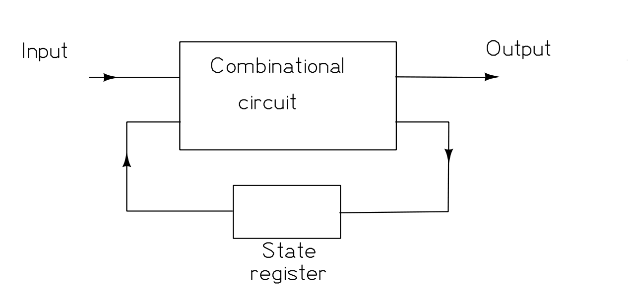
Figure: a finite state machine, with a state register and combinational logic around it
It has five parts worth naming separately.
Finite States
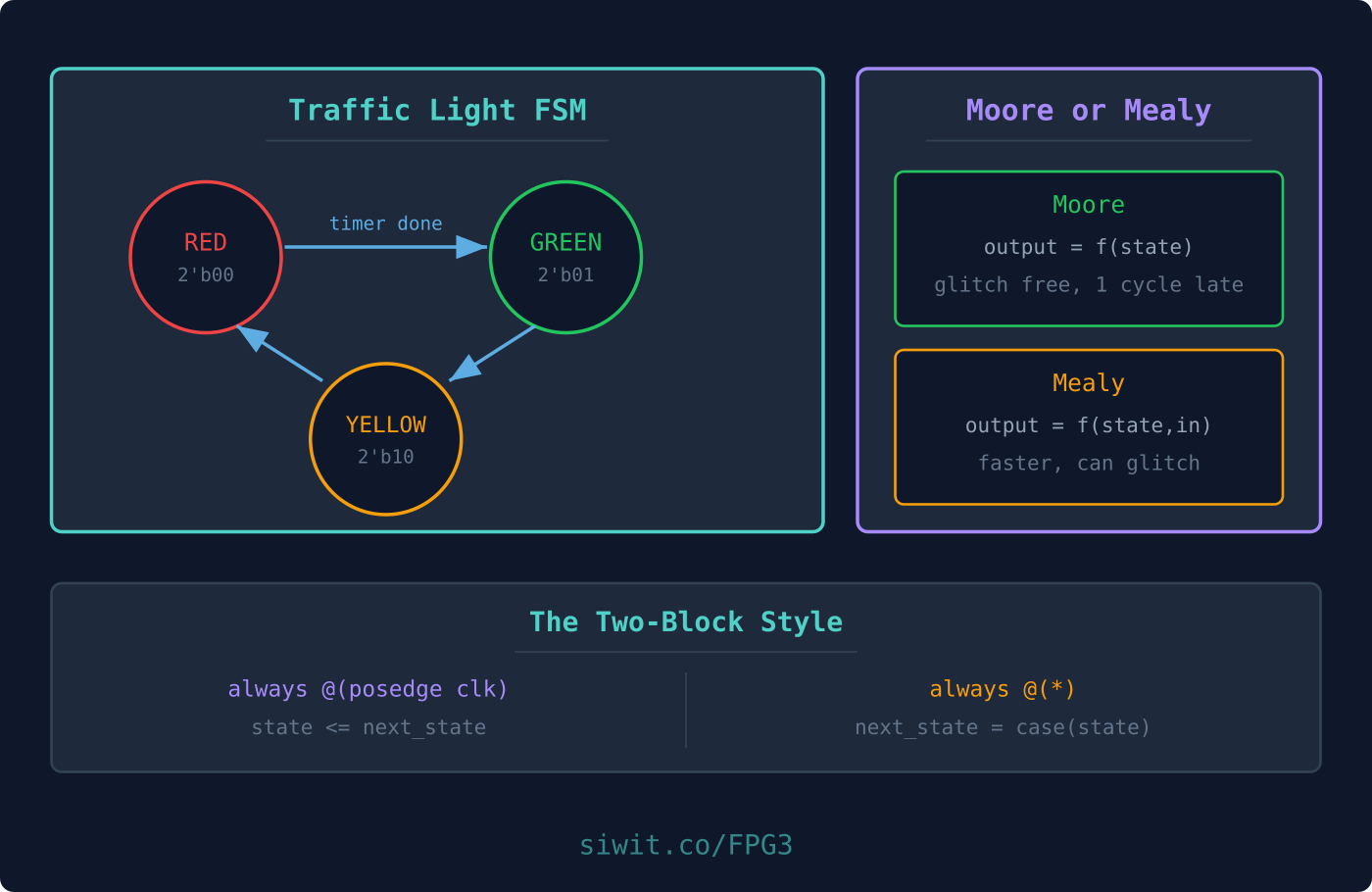
The complete list of situations the machine can be in. There must be a finite number of them, hence the name, and the machine is in exactly one at any moment. A traffic light has three: red, green, yellow.
State Transitions
The moves from one state to another. A transition happens on a clock edge, never between edges. That is what makes the design predictable.
State Diagram
A drawing with one bubble per state and one arrow per transition, labelled with the condition that causes it. Draw this before writing any Verilog. Almost every FSM bug is visible in a state diagram, and almost none are visible in code you wrote without one.
Inputs
What the machine looks at when deciding whether to move. A timer expiring, a button press, a byte arriving.
Outputs
What the machine drives. Which lamp is lit, whether a busy flag is high, what value goes on a bus.
Moore versus Mealy
There are two kinds of FSM, and the difference is only about where the outputs come from.
Mealy State Machine
A Mealy machine’s outputs depend on both the present inputs and the present state.
Figure: Mealy machine, with outputs taken from state and input together
It has combinational logic and a state register. The register holds the present state, and the combinational logic derives both the next state and the outputs from that state plus the current inputs.
State Diagram of a Mealy Machine
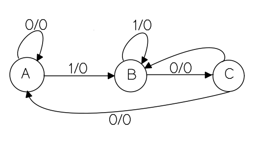
Figure: Mealy state diagram, labelled input/output on each arrow
There are three states, A, B and C. The label 0/0 on an arrow means input/output. So at state A, an input of 0 keeps the output at 0 and stays in A. An input of 1 at state A also gives output 0, but moves to state B.
Notice that the output is written on the arrow, not in the bubble. That is the visual signature of a Mealy machine.
State Table for a Mealy Machine
Present State
Input
Next State
Output
A
0
A
0
A
1
B
0
B
0
C
0
B
1
B
0
C
0
A
0
C
1
-
-
The dash in the last row marks a combination that cannot occur, or that the specification does not define. In real code you still have to decide what happens there, which is why every case statement needs a default.
Moore State Machine
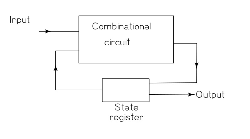
A Moore machine’s outputs depend only on the present state.
There are still two parts, combinational logic and a state register. Present inputs and present state determine the next state, and the output is then derived from the state alone.
Figure: Moore machine, with outputs taken from the state register only
State Diagram of a Moore Machine
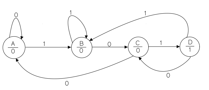
Figure: Moore state diagram, output written inside each state bubble
State Table for a Moore Machine
Present State
Input
Next State
Output
A
0
A
0
A
1
B
0
B
0
C
0
B
1
D
0
C
0
A
0
C
1
D
0
D
0
C
1
D
1
B
1
Look at the last two rows. The output is 1 for both, because both are state D. In a Moore machine the input never appears in the output column, which is exactly the property that makes them easier to reason about.
Choosing between them
Moore
Mealy
Output depends on
State only
State and input
Reacts
One clock later
Immediately
Glitches
Cannot, if registered
Possible, since inputs pass through
States needed
Often more
Often fewer
Easier to verify
Yes
No
Default to Moore. The output is a clean function of a registered value, so it is stable for a whole clock period and cannot glitch. Reach for Mealy when a one-cycle delay genuinely costs you something, for example when you must assert a handshake in the same cycle a request arrives.
State Encoding: Binary versus One-Hot
States are an idea. Flip-flops are the reality, so the state has to be a number.
Binary encoding uses the fewest bits. Three states fit in two bits:
Two flip-flops hold the state. The cost is that decoding “am I in state GREEN?” needs a comparison across both bits, so wide binary state registers grow slow decode logic.
One-hot encoding uses one bit per state, with exactly one bit high:
Three flip-flops now, but testing a state is a single-bit read, and the next-state logic often collapses to almost nothing.
On an FPGA, one-hot is frequently the better trade. Flip-flops are abundant, sitting next to every LUT whether you use them or not, while logic depth is what limits your clock speed. Trading spare flip-flops for shallower logic is usually a win. On an ASIC, where every flip-flop costs area and power, the balance shifts back toward binary.
In practice, write the encoding as named localparam values and let the synthesis tool re-encode if it wants to. Most tools do this well, and named constants keep the code readable either way.
Use localparam rather than parameter for state encodings. A parameter can be overridden from outside the module, and nobody should be able to redefine what GREEN means.
The Two-Block Coding Style
An FSM is easy to write badly. The style below is the one to learn, because it maps directly onto the hardware and it is hard to get subtly wrong.
Block one is clocked and does nothing but move the state forward:
Block 1: the state register
always @(posedge clk) begin
if (rst) state <= S_RED;
else state <= next_state;
end
Block two is combinational and decides where to go next:
A Moore machine adds a third combinational block for the outputs, driven from state alone:
Block 3: output logic, Moore style
always @(*) begin
case (state)
S_RED: {red, yellow, green} =3'b100;
S_GREEN: {red, yellow, green} =3'b001;
S_YELLOW: {red, yellow, green} =3'b010;
default: {red, yellow, green} =3'b100;
endcase
end
Four rules that come with the style:
<= in the clocked block, = in the combinational blocks. The rule from Lesson 1, and it matters most here.
Every case needs a default. Without it, an unlisted state has no assignment, which infers a latch in combinational logic and can leave the machine stuck.
Assign next_state on every path. Same reason. A case that assigns nothing in one branch is a latch.
Reset to a named state. Never rely on power-up values.
Building the Traffic Light Controller
Specifications
State
Red
Yellow
Green
Duration
RED
1
0
0
5 sec
GREEN
0
0
1
5 sec
YELLOW
0
1
0
2 sec
Note the order the states run in: red, then green, then yellow, then back to red. Yellow warns that green is ending, so it belongs after green, not before it. Getting the sequence wrong is a specification bug rather than a coding bug, and no amount of Verilog skill will catch it for you. Draw the state diagram first.
Turning seconds into clock ticks
An FPGA has no notion of seconds, only clock edges. If the board gives you a 27 MHz clock, then five seconds is 135,000,000 ticks. Rather than bury those numbers in the logic, make them parameters:
The line that carries the whole design is ticks <= 0 on a state change. Each state then measures elapsed time from when it was entered, rather than waiting for the counter to reach some absolute value. The next section shows what happens without it.
Parameters also make the design testable. Simulating 50 million clock cycles is unpleasant; overriding the parameters to 50 makes the same logic verifiable in milliseconds:
The property to test is not “does it compile” but “does each state last the number of ticks it should”. This testbench measures the duration of every state and compares it:
YELLOW: next_state = (counter ==26'd20000000) ? GREEN : YELLOW;
GREEN: next_state = (counter ==26'd50000000) ? RED : GREEN;
default: next_state = RED;
endcase
end
It compiles, and the lights do change. The durations are wrong. Explain why, and predict what actually happens.
Click to reveal the solution
Notice what the counter measures. It counts continuously from reset and is never cleared, so counter is absolute time, not time spent in the current state. ✅
Follow the first transition. RED waits until counter reaches 50,000,000, then moves to YELLOW. Correct so far, because RED happened to start at zero. ✅
Follow the second. YELLOW waits for counter == 20,000,000. But the counter is already at 50,000,000 and still rising, so that value is in the past. YELLOW cannot leave until the counter wraps all the way round its 26-bit range and climbs back to 20,000,000. ✅
Predict the numbers. With a 26-bit counter wrapping at 67,108,864, YELLOW lasts (67,108,864 - 50,000,000) + 20,000,000, roughly 37 million ticks instead of 20 million. GREEN then waits from 20,000,000 up to 50,000,000, so 30 million instead of 50 million. ✅
Confirm by scaling down. Shrink the counter to 6 bits and the thresholds to 50, 20 and 50, and simulate. Against a spec of RED 50, YELLOW 20, GREEN 50, the measured steady-state durations are RED 64, YELLOW 34, GREEN 30. Every one is wrong, and none of them is wrong by a simple factor, which is why this bug is so confusing to chase by eye. ✅
Fix it by clearing the counter whenever the state changes, so each state measures elapsed time. Comparing with a per-state limit then means what you intended. ✅
The general lesson: a timer inside an FSM should measure time in the current state. An absolute counter shared across states only works if you also recompute every threshold, which nobody maintains correctly for long.
Question 2: A state machine that locks up after reset
An FSM works in simulation but, on power-up without an explicit reset, it sometimes freezes and never leaves its first state. What design habit prevents this?
Click to reveal the solution
Identify the cause. Without a reset, the state register can power up in an undefined or unreachable state, with no transition out of it. ✅
Add a synchronous reset that forces a known starting state, and make sure every defined state has a path back toward normal operation. ✅
Add a default branch in the next-state logic so any unexpected state value returns to a safe state rather than sticking. ✅
Understand why unreachable states exist at all. Three states encoded in two bits leaves 2'd3 unused. It should never occur, but a glitch, a single-event upset, or an incomplete reset can produce it, and default is what recovers from it. ✅
Question 3: Would Mealy have saved a state?
A design must assert a one-cycle done pulse the moment a start input goes high while the machine is idle. A colleague implements it as Moore, and finds they need an extra state whose only job is to emit the pulse. Was Mealy the better choice?
Click to reveal the solution
Understand why Moore needed the extra state. A Moore output is a function of state alone, so producing a pulse requires being in a state that means “pulsing”. That state exists purely to carry the output. ✅
See what Mealy does instead. A Mealy output can be a function of state and input together, so done can be asserted directly from the idle state when start is high, with no extra state at all. ✅
Weigh the cost. The Mealy output passes combinational logic from start to done, so it can glitch, and it is asserted in the same cycle rather than one later. If a downstream block samples done on a clock edge, glitches between edges are harmless. If it feeds an asynchronous input, they are not. ✅
Answer. Yes, Mealy is the better choice here, provided done is consumed synchronously. If it is not, keep the Moore version and accept the extra state, because a clean output is worth one flip-flop. ✅
Summary
Concept
Key Takeaway
FSM
States, transitions, inputs and outputs that capture sequential behaviour
State diagram
Draw it before writing Verilog. Most FSM bugs are visible there and invisible in code
Moore versus Mealy
Moore output depends on state only, Mealy also on input. Default to Moore
Encoding
Binary is compact, one-hot trades spare flip-flops for shallower logic and often wins on FPGAs
localparam
Use it for state encodings, so nothing outside can redefine them
Two-block style
Clocked state register, combinational next-state logic, plus an output block for Moore
default
Every case needs one, or you infer a latch and risk lock-up
Timers in an FSM
Measure elapsed time in the current state. Clear the counter on every transition
Parameters
Make durations parameters, so the same logic is testable at simulation speed
You can now build a circuit that remembers, times itself, and recovers from an illegal state. Everything so far has lived in a simulator. Next it goes onto real hardware.



Comments