Every design so far has run on one clock, where everything is predictable. Real systems are not like that. An ADC has its own oscillator, a camera sends pixels on its own clock, a UART arrives at whatever rate the other end chose. The moment two unrelated clocks meet, a whole class of intermittent, unreproducible bug becomes available to you, and this lesson is about not writing it. #verilog #fpga #cdc
Learning Objectives
By the end of this lesson, you will be able to:
Write Verilog that infers block RAM rather than a pile of flip-flops.
Build a synchronous FIFO with correct full and empty behaviour.
Explain metastability and why one flip-flop is not enough.
Apply the two-flop synchroniser, and say exactly when it is not sufficient.
Build a dual-clock FIFO with Gray-coded pointers, and verify it across unrelated clocks.
What We Are Building
Two FIFOs and a synchroniser
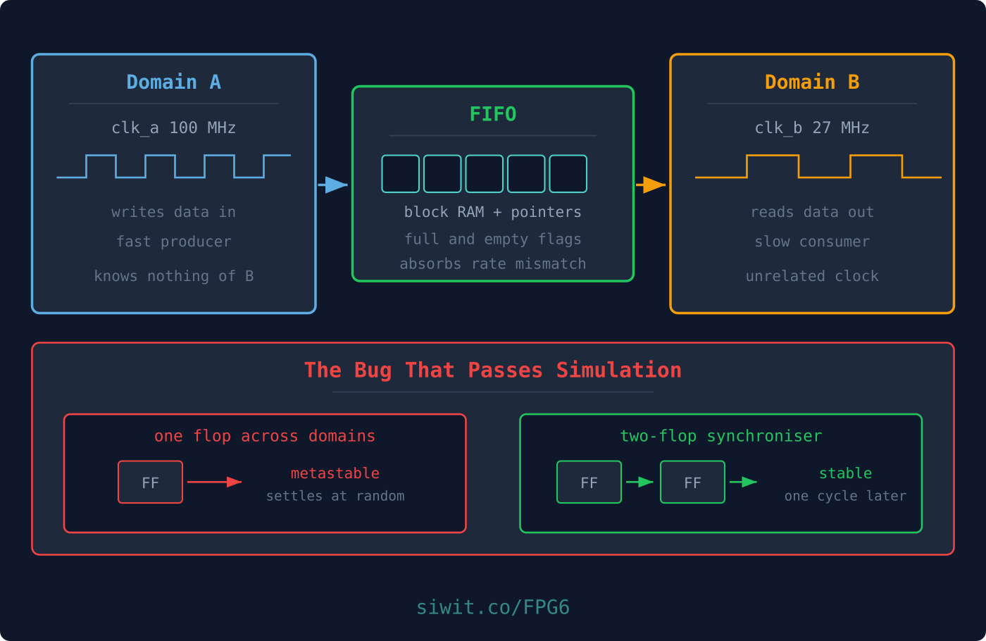
A synchronous FIFO first, to get the pointer and flag logic right on one clock. Then the two-flop synchroniser for single-bit signals. Then the real thing: a dual-clock FIFO with Gray-coded pointers, tested with a 100 MHz writer feeding a 27 MHz reader.
Inferring Block RAM
Lesson 4 mentioned that FPGAs contain dedicated block RAM. You do not instantiate it explicitly. You write Verilog that looks like a memory, and the synthesis tool recognises the pattern and maps it.
simple_ram.v
module simple_ram #(
parameterinteger WIDTH =8,
parameterinteger DEPTH =256,
parameterinteger AW =8
) (
inputwire clk,
inputwire we,
inputwire [AW-1:0] addr,
inputwire [WIDTH-1:0] din,
outputreg [WIDTH-1:0] dout
);
reg [WIDTH-1:0] mem [0:DEPTH-1];
always @(posedge clk) begin
if (we) mem[addr] <= din;
dout <= mem[addr]; // registered read: this is what makes it block RAM
end
endmodule
The pattern that matters is dout <= mem[addr] inside a clocked block. A registered read is what block RAM offers, so writing it that way lets the tool use one. Write it as assign dout = mem[addr] instead and you have asked for a combinational read, which block RAM cannot do, so the tool builds the whole array out of LUTs and flip-flops. On a small FPGA that will exhaust the fabric in a hurry.
The practical consequences:
Read data arrives one cycle after the address. Every design using block RAM has that latency in it, so plan for it rather than discovering it.
Check the synthesis log. Yosys reports how many RAM blocks it inferred. If you expected one and see zero, your read was combinational or your array was indexed in a way the tool could not recognise.
Do not initialise it in an initial block unless your device supports it. Some do, some do not, and the code silently means different things.
Building a Synchronous FIFO
A FIFO is memory plus two pointers and two flags. On a single clock it is straightforward, and getting it right here is worth doing before adding the complication of a second clock.
sync_fifo.v
module sync_fifo #(
parameterinteger WIDTH =8,
parameterinteger DEPTH =8,
parameterinteger AW =3// log2(DEPTH)
) (
inputwire clk,
inputwire rst,
inputwire wr_en,
inputwire [WIDTH-1:0] wr_data,
inputwire rd_en,
outputreg [WIDTH-1:0] rd_data,
outputwire full,
outputwire empty,
outputreg [AW:0] count
);
reg [WIDTH-1:0] mem [0:DEPTH-1];
reg [AW-1:0] wr_ptr, rd_ptr;
assign full = (count == DEPTH);
assign empty = (count ==0);
always @(posedge clk) begin
if (rst) begin
wr_ptr <=0; rd_ptr <=0; count <=0; rd_data <=0;
endelsebegin
if (wr_en &&!full) begin
mem[wr_ptr] <= wr_data;
wr_ptr <= wr_ptr +1'b1;
end
if (rd_en &&!empty) begin
rd_data <= mem[rd_ptr];
rd_ptr <= rd_ptr +1'b1;
end
// count changes only when exactly one of the two actually happens
if ((wr_en &&!full) &&!(rd_en &&!empty)) count <= count +1'b1;
A separate count register makes full and empty trivial. The alternative, comparing pointers, needs an extra bit to distinguish “pointers equal because empty” from “pointers equal because full”, which is the trick the dual-clock version will have to use.
Writes are gated on !full and reads on !empty. Without those guards a caller who ignores the flags silently corrupts the buffer. Enforce it inside.
Simultaneous read and write leave count unchanged, which is correct and easy to get wrong.
Verified on five separate properties:
Simulation output
empty after reset ............... PASS
full after 8 writes ............ PASS (count=8)
overflow write ignored ......... PASS (count=8)
first-in-first-out order ....... PASS
empty after draining ........... PASS (count=0)
The overflow test matters more than it looks. A FIFO that silently accepts a write when full is worse than one that blocks, because the corruption appears later and somewhere else.
Metastability: Why One Flip-Flop Is Not Enough
Here is the physical fact underneath everything in the rest of this lesson.
A flip-flop captures its input on a clock edge, but only reliably if the input has been stable for a short period before the edge (setup time) and stays stable briefly after it (hold time). Those windows are a few hundred picoseconds on a modern FPGA.
If an input changes inside that window, the flip-flop does not cleanly capture a 0 or a 1. It enters a metastable state, sitting at an intermediate voltage, and it resolves to one value or the other after an unpredictable delay.
What metastability looks like
setup | | hold
v v
clk ______________|‾‾‾|________________
input ‾‾‾‾‾‾‾‾‾‾‾‾‾‾\____________________ changes inside the window
output ‾‾‾‾‾‾‾‾‾‾‾‾‾‾‾‾~~~~~~~~\_______ undecided, then resolves
^^^^^^^
metastable, duration unpredictable
Two things make this the nastiest class of bug in digital design:
It is a probability, not a certainty. With unrelated clocks, the chance that a given edge lands in the window is small, so a design can run for hours and then fail. The industry metric is literally mean time between failures.
Simulation will not show it. A standard simulator has no notion of setup windows. It captures either the old value or the new one, cleanly. Your CDC bug will pass every simulation you write and then fail on hardware, which is why this must be handled by discipline rather than by testing.
You cannot prevent metastability. Asynchronous inputs exist. What you can do is give it time to resolve before anything acts on it.
The Two-Flip-Flop Synchroniser
The standard fix for a single-bit signal crossing domains:
synchronizer.v
module synchronizer (
inputwire clk,
inputwire async_in,
outputwire sync_out
);
reg ff1, ff2;
always @(posedge clk) begin
ff1 <= async_in;
ff2 <= ff1;
end
assign sync_out = ff2;
endmodule
The first flip-flop may go metastable. It then has a full clock period to settle before the second one samples it. The probability that it is still undecided a whole period later is vanishingly small, and the second flip-flop’s output is therefore clean. The cost is one cycle of latency and, at reset, one cycle of an undefined value.
You have already used this twice without it being named: on the button in Lesson 4 and on the rx line in Lesson 5.
Now the critical limitation. A two-flop synchroniser is safe for one bit and one bit only.
Put one on each bit of a multi-bit bus and you have built something worse than nothing. Each bit resolves independently, so when the bus changes from 0111 to 1000, individual bits can land on different sides of the edge, and the receiving domain can capture 1111 or 0000, values the counter never held. This is the single most common CDC mistake, and it is the subject of Question 1 below.
For a bus you need either a FIFO, or Gray coding so that only one bit ever changes at a time.
Crossing a Bus: The Dual-Clock FIFO
This is the workhorse. Data goes into memory in the write domain and comes out in the read domain, and the only things that cross are the two pointers, Gray coded so each is safe to synchronise.
Why Gray code
In Gray code, consecutive values differ in exactly one bit:
Binary
Gray
000
000
001
001
010
011
011
010
100
110
101
111
110
101
111
100
That single-bit property is the whole point. When a Gray-coded pointer increments, only one bit changes, so synchronising it can only ever give you the old value or the new one. Never a mixture, because there is no mixture to have. Converting is one line:
Binary to Gray
function [AW:0] bin2gray(input [AW:0] b);
bin2gray = b ^ (b >>1);
endfunction
The FIFO
async_fifo.v
module async_fifo #(
parameterinteger WIDTH =8,
parameterinteger AW =3// depth = 2**AW
) (
// write domain
inputwire wclk,
inputwire wrst,
inputwire wr_en,
inputwire [WIDTH-1:0] wr_data,
outputreg full,
// read domain
inputwire rclk,
inputwire rrst,
inputwire rd_en,
outputwire [WIDTH-1:0] rd_data,
outputreg empty
);
localparaminteger DEPTH =1<< AW;
reg [WIDTH-1:0] mem [0:DEPTH-1];
// Pointers carry one extra bit so full and empty stay distinguishable
reg [AW:0] wbin, wgray, rbin, rgray;
reg [AW:0] wgray_r1, wgray_r2; // wgray synchronised into the read domain
reg [AW:0] rgray_w1, rgray_w2; // rgray synchronised into the write domain
function [AW:0] bin2gray(input [AW:0] b);
bin2gray = b ^ (b >>1);
endfunction
// ---------------- write domain ----------------
// full is REGISTERED. Deriving it combinationally would create a loop,
// ---------------- the two-flop synchronisers ----------------
always @(posedge rclk) begin
if (rrst) begin wgray_r1 <=0; wgray_r2 <=0; end
elsebegin wgray_r1 <= wgray; wgray_r2 <= wgray_r1; end
end
always @(posedge wclk) begin
if (wrst) begin rgray_w1 <=0; rgray_w2 <=0; end
elsebegin rgray_w1 <= rgray; rgray_w2 <= rgray_w1; end
end
endmodule
Read it in three passes.
The pointers have an extra bit. A depth-8 FIFO uses 4-bit pointers. When the low three bits match but the top bit differs, the writer has lapped the reader, which means full. When all four match, empty. Without that bit the two conditions are indistinguishable.
Only Gray-coded pointers cross.wgray goes through two flip-flops into the read domain, rgray likewise into the write domain. The data itself never crosses; it sits in memory, written by one clock and read by the other at a different address.
The flags are conservative by construction. Each domain sees a synchronised pointer that is one or two cycles stale, so full may assert slightly early and empty may clear slightly late. Both errors are in the safe direction. The dangerous direction, thinking there is space when there is not, cannot happen.
The full comparison, wgray_next == {~rgray_w2[AW:AW-1], rgray_w2[AW-2:0]}, is checking whether the next write pointer equals the read pointer with the top two bits inverted, which is the Gray-code equivalent of “one lap ahead”.
Verified across unrelated clocks
The test that matters uses two clocks with no integer relationship, so the phase between them drifts continuously:
Excerpt from the testbench
always#5 wclk =~wclk; // 100 MHz writer
always#18.5 rclk =~rclk; // about 27 MHz reader, deliberately unrelated
Simulation output
wrote 40 bytes at 100 MHz, read 40 at 27 MHz
every byte in order, none lost or duplicated ... PASS
Forty bytes through a depth-8 FIFO means the writer filled it and blocked repeatedly while the reader drained, so both flags were exercised under back-pressure rather than in a quiet run.
Remember, though, what simulation can and cannot tell you here. It confirms the protocol is right: pointers, flags, ordering, no loss. It says nothing about metastability, which it does not model. That part rests on the two-flop synchronisers being present and the pointers being Gray coded.
Application Questions and Solutions
Question 1: The bug that only appears in hardware
A data path passes a multi-bit counter value from a fast clock to a slow one using a two-flip-flop synchroniser on each bit. It works most of the time but occasionally reads a wildly wrong value. Why?
Click to reveal the solution
Spot the misuse. A two-flip-flop synchroniser is safe for a single bit only. Across a multi-bit bus, individual bits can settle on different clock edges. ✅
Understand the result. During a transition the captured word can mix old and new bits, giving a value that never actually existed. A counter going from 0111 to 1000 can be read as 1111 or 0000. ✅
See why “wildly wrong” is the giveaway. An off-by-one would suggest a latency mistake. A value far from both the old and the new one means bits were mixed, which points straight at per-bit synchronisation. ✅
Use the right structure. Pass the data through a FIFO, or convert the pointer to Gray code so only one bit changes at a time. ✅
Question 2: The simulator hangs instead of failing
While writing the dual-clock FIFO, a developer derives the full flag combinationally:
The version that hangs
wire [AW:0] wbin_next = wbin + (wr_en &&!full);
wire [AW:0] wgray_next = bin2gray(wbin_next);
assign full = (wgray_next == {~rgray_w2[AW:AW-1], rgray_w2[AW-2:0]});
The simulation produces no output at all and has to be killed. What is wrong, and why does it hang rather than report an error?
Click to reveal the solution
Trace the dependencies.full depends on wgray_next, which depends on wbin_next, which depends on full. That is a combinational loop with no register to break it. ✅
Understand the hang. Each change to full forces a re-evaluation that changes full again, at the same simulation time. The simulator never advances, so it produces no output and never terminates. It is not an error it can detect, it is a circuit that has no settled state. ✅
Recognise the hardware equivalent. In real silicon this is a ring oscillator: a loop of gates feeding itself, oscillating at whatever frequency the propagation delay allows. Synthesis will usually warn, and the result is unusable. ✅
Fix it by registering the flag. Compute full_next combinationally, then assign it to a registered full on the clock edge. The loop is broken because wbin_next now depends on the previous cycle’s value. ✅
The general lesson: if a simulation hangs with no output rather than failing a check, suspect a combinational loop before you suspect the testbench.
Question 3: When is a FIFO the wrong answer?
A single-bit enable from a slow control domain needs to reach a fast datapath domain. A colleague proposes a dual-clock FIFO. Is that right?
Click to reveal the solution
Match the tool to the problem. A FIFO exists to move multi-bit data while preserving order and absorbing rate mismatch. A single-bit level needs none of that. ✅
Use a two-flop synchroniser instead. One bit, no ordering requirement, no buffering. Two flip-flops and one cycle of latency. ✅
Note the one real trap. If the signal is a pulse rather than a level, and the source clock is faster than the destination, the pulse can be too short to be sampled at all. That needs a pulse stretcher or a toggle-and-synchronise handshake, not a FIFO. ✅
Answer. No. A FIFO here is a large amount of block RAM and logic to solve a problem two flip-flops solve, and it adds latency for nothing. ✅
Summary
Concept
Key Takeaway
Block RAM inference
Use a registered read, dout <= mem[addr], inside a clocked block
Read latency
Block RAM data arrives one cycle after the address. Design around it
Synchronous FIFO
Memory plus two pointers plus flags. Gate writes on full and reads on empty
Metastability
An input changing in the setup window leaves a flip-flop briefly undecided
Simulation blind spot
Simulators do not model metastability. CDC correctness comes from discipline, not testing
Two-flop synchroniser
The standard fix, for exactly one bit
Per-bit synchronisers on a bus
The most common CDC bug. Produces values that never existed
Gray code
Consecutive values differ in one bit, so a synchronised pointer is old or new, never mixed
Dual-clock FIFO
Only Gray-coded pointers cross. Data stays in memory
Extra pointer bit
Needed so full and empty are distinguishable when pointers match
Conservative flags
Stale synchronised pointers make full early and empty late. Both are safe
Combinational loops
A simulation that hangs with no output usually means one. Register the flag
You can now store data, buffer it, and move it between clocks without corrupting it. That is the last building block you need before assembling them into something that executes a program.



Comments