Describe hardware, not software
Write Verilog that synthesises into real gates and flip-flops. Understand the difference between combinational and sequential logic, blocking and non-blocking assignments, and why hardware is parallel by nature.
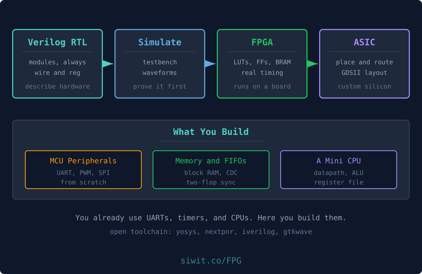
You already use UARTs, timers, PWM channels, and CPU cores every time you program a microcontroller. This course teaches you to build them. You will describe digital hardware in Verilog, prove it works in simulation, run it on a real FPGA, and finish by pushing a design through the open-source ASIC flow to a manufacturable layout. #fpga #verilog #digitaldesign
Describe hardware, not software
Write Verilog that synthesises into real gates and flip-flops. Understand the difference between combinational and sequential logic, blocking and non-blocking assignments, and why hardware is parallel by nature.
Verify before you build
Write self-checking testbenches and read waveforms, so a design is proven correct in simulation before it ever touches a board.
Run it on real silicon
Take a Verilog design through synthesis, place and route, and timing on a low-cost FPGA using a fully open toolchain.
Build the blocks inside an MCU
Create the peripherals you normally take for granted, a UART, a PWM generator, an SPI master, and even a small CPU, from scratch in hardware.
Lesson 1: Verilog Fundamentals
Start here. Modules, ports, wires and registers, combinational versus sequential logic, and your first testbench. Practical: recreate logic gates and a 4-bit adder in Verilog and simulate them.
Lesson 2: Simulation and Testbenches
Open lesson. Why you simulate first, testbench structure, stimulus, self-checking assertions, and waveform analysis. Practical: write a self-checking testbench and inspect signals in GTKWave.
Lesson 3: State Machines in Verilog
Open lesson. Finite state machines, Moore versus Mealy, state encoding, and the clean two-block coding style. Practical: a traffic-light controller and a protocol-decoder FSM.
Lesson 4: First Design on a Real FPGA
Open lesson. FPGA architecture (LUTs, flip-flops, block RAM), the open toolchain, pin constraints, and timing. Practical: blink and a debounced counter on an iCE40 board.
Lesson 5: Building MCU-Style Peripherals
Open lesson. PWM generators, UART transmit and receive, SPI, and shift registers in pure hardware. Practical: a UART transmitter and a PWM LED dimmer running on the FPGA.
Lesson 6: Memory, FIFOs, and Clock-Domain Crossing
Open lesson. Inferring block RAM, building FIFOs, metastability, synchronisers, and crossing clock domains safely. Practical: a dual-clock FIFO passing data between two clock domains.
Lesson 7: Building a Mini CPU
Open lesson. Datapath, ALU, register file, program counter, and instruction decode for a tiny instruction set. Practical: an 8-bit CPU that executes a small program from memory.
Lesson 8: FPGA plus MCU Co-Design
Open lesson. When to choose FPGA versus MCU versus DSP, system-on-chip concepts, soft cores, and interfacing an FPGA to an MCU. Practical: an FPGA accelerator that talks to an STM32 or ESP32 over SPI.
Lesson 9: From FPGA to ASIC
Open lesson. The ASIC flow from RTL through synthesis, floorplan, place and route, to GDSII, using the Sky130 PDK and LibreLane. Practical: take an earlier Verilog block all the way to a manufacturable layout.
Open simulation toolchain
Icarus Verilog for simulation and GTKWave for waveform viewing. Both are free, cross-platform, and used from Lesson 1, so you can complete the first three lessons with no hardware at all.
Open FPGA toolchain
Yosys for synthesis, nextpnr for place and route, and the board flashing tools. A fully open flow with no vendor licences.
A low-cost FPGA board
A Tang Nano 9K (roughly 15 to 20 USD) is the recommended board from Lesson 4 onward, with iCE40 boards such as the iCEBreaker or iCEstick as a documented alternative. Lessons 1 to 3 need no hardware at all.
Open ASIC toolchain
The Sky130 open process design kit and LibreLane, used in the final lesson to turn RTL into a GDSII layout.
Comes after: Digital Electronics
Digital Electronics and Logic teaches the logic principles this course assumes. Take it first if gates and flip-flops are new to you.
Pairs with: Embedded Programming
Feeds into: Sensor and Actuator Interfacing
Custom hardware interfaces connect naturally to the sensor and actuator interfacing course when you need deterministic, high-speed I/O.