Protocol to Device
Each lesson pairs a protocol (GPIO, ADC, PWM, I2C, SPI, UART, CAN) with real sensors and actuators. You do not just read a datasheet; you wire, configure, code, and verify the device on your bench.
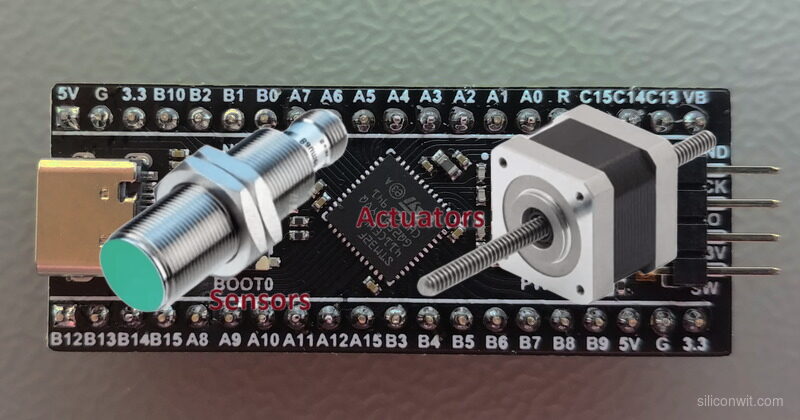
Knowing how to configure a timer or set up a UART peripheral is one thing. Knowing how to connect an RFID reader, drive a stepper motor to a precise position, or parse GPS coordinates from a serial stream is another. This course bridges that gap. Every lesson pairs a communication protocol with real hardware you can hold in your hand, and every project does something useful when you are done building it. #STM32 #Interfacing #Sensors
The Embedded Programming: STM32 course taught the internals: clock trees, register access, DMA channels, linker scripts. That foundation matters, but most embedded work involves connecting external devices and making them cooperate. This course focuses entirely on that external world.
Protocol to Device
Each lesson pairs a protocol (GPIO, ADC, PWM, I2C, SPI, UART, CAN) with real sensors and actuators. You do not just read a datasheet; you wire, configure, code, and verify the device on your bench.
Industry-Relevant Hardware
The parts list covers what engineers actually use: BME280, MPU6050, OLED displays, RFID readers, GPS modules, stepper drivers, CAN transceivers. These are the components that show up in product designs, not toy peripherals.
CubeMX Visual Configuration
STM32CubeIDE with its built-in CubeMX lets you visually assign pins, configure clock trees, and generate HAL initialization code. For an interfacing course, this is the right tool: you see which pins support I2C1 or SPI2, resolve conflicts graphically, and focus your time on the device driver logic rather than register bit-twiddling.
From Single Device to System
Lessons build toward a capstone that combines multiple sensors, an SD card, an OLED display, Bluetooth streaming, and alarm outputs into one integrated system. You learn not just how to talk to each device, but how to manage multiple peripherals sharing the same bus.
The Embedded Programming: STM32 course used the bare toolchain (arm-none-eabi-gcc, OpenOCD, make) because the goal was to understand what happens at the register level: startup code, linker scripts, vector tables, and raw peripheral access. That knowledge is valuable and this course assumes you have it.
For interfacing, the priorities shift. You are configuring I2C buses, SPI chip selects, UART baud rates, ADC channels, DMA streams, and CAN bit timing, sometimes several of these on the same project. Doing all of that through raw register writes is slow and error-prone when the goal is to get a sensor talking. CubeIDE with CubeMX gives you:
When to use the bare toolchain instead: Custom bootloaders, safety-critical firmware that must be audited line by line, extremely tight flash constraints where HAL overhead matters, or CI/CD pipelines where a headless Makefile build is simpler. If you need to strip a binary down to 4 KB or certify every line of code for automotive/medical, the bare toolchain gives you that control. For everything else, CubeIDE is faster and less error-prone.
Both toolchains produce the same ARM binary. CubeIDE generates a Makefile project you can export and build from the command line if you ever need to.
Each lesson follows a consistent cycle:
The Interfacing Challenge A real device that needs to communicate with the STM32. Not a toy example, but a sensor, actuator, or module you would find in a product design.
Protocol and Wiring How the protocol works (timing, addressing, data framing), the wiring diagram with pin assignments, and the CubeMX configuration for the peripheral.
Build the Driver Write the HAL-based driver code, read/write to the device, handle errors. Every code block compiles and runs on the Blue Pill.
Test and Verify Flash, connect, measure. Use a multimeter, logic analyzer, or serial terminal to confirm the device responds correctly.
Production Notes What changes when you move from a breadboard to a PCB: pull-up values, decoupling, ESD protection, bus speed limits, and power considerations.
Lesson 1: GPIO and Digital Interfacing
GPIO and Digital Interfacing. Set up STM32CubeIDE, configure GPIO inputs and outputs with the HAL, and interface digital devices. Implement hardware debouncing, use interrupts for responsive input handling, and drive a relay module. Build: Ultrasonic proximity alarm with relay trigger. Parts: HC-SR04, relay module, buzzer, push button.
Lesson 2: ADC and Analog Signal Conditioning
ADC and Analog Signal Conditioning. Configure the 12-bit ADC with single, continuous, and scan modes. Add signal conditioning circuits (voltage dividers, RC filters, op-amp buffers) to interface analog sensors cleanly. Build: Multi-channel environmental monitor with LED bar graph. Parts: Thermistor (NTC 10K), LDR, potentiometer, op-amp (LM358).
Lesson 3: PWM, Timers, and Motor Control
PWM, Timers, and Motor Control. Generate PWM signals with hardware timers for servo positioning, DC motor speed control, and audio tone generation. Use input capture to measure external signals. Build: Servo pan-tilt mount with DC motor speed control. Parts: 2x SG90 servo, DC motor, L298N H-bridge, potentiometers, passive buzzer.
Lesson 4: I2C Protocol: Sensors and Displays
I2C Protocol: Sensors and Displays. Master I2C communication with multiple devices on a shared bus. Read environmental data, drive an OLED display, and store readings in EEPROM. Handle bus scanning, addressing, and error recovery. Build: Weather station with OLED display and EEPROM logging. Parts: BME280, SSD1306 OLED (128x64), AT24C256 EEPROM.
Lesson 5: SPI Protocol: Storage and Displays
SPI Protocol: Storage and Displays. Configure SPI with proper clock polarity, phase, and chip select management. Interface a color TFT display and an SD card on the same SPI bus using FatFS for file operations. Build: Portable data logger with color TFT display. Parts: ST7735 TFT (1.8”), microSD card module, microSD card.
Lesson 6: UART Devices: GPS, Bluetooth, and RS-485
UART Devices: GPS, Bluetooth, and RS-485. Parse NMEA sentences from a GPS module, relay data over Bluetooth to a phone, and communicate over long distances with RS-485 differential signaling. Use DMA for efficient UART reception. Build: GPS tracker with Bluetooth phone relay. Parts: NEO-6M GPS module, HC-05 Bluetooth module, MAX485 transceiver.
Lesson 7: RFID, NFC, and Identification Systems
RFID, NFC, and Identification Systems. Interface the RC522 RFID reader over SPI, read and write MIFARE cards, build an access control state machine with visual and audio feedback. Store authorized card UIDs in EEPROM. Build: RFID door access control system. Parts: RC522 RFID module, MIFARE cards/tags, SSD1306 OLED, buzzer, LED.
Lesson 8: Stepper Motors and Encoder Feedback
Stepper Motors and Encoder Feedback. Drive stepper motors with acceleration profiles using the A4988 driver. Read rotary encoder position with timer encoder mode. Implement closed-loop positioning with limit switches for homing. Build: Precision linear positioning stage. Parts: NEMA 17 stepper, A4988 driver, rotary encoder, 2x limit switches, 12V supply.
Lesson 9: DMA, Interrupts, and CAN Bus
DMA, Interrupts, and CAN Bus. Use DMA for zero-copy ADC streaming and SPI transfers. Configure the STM32’s built-in bxCAN peripheral for automotive-grade communication. Build a two-node CAN network with message filtering and error handling. Build: CAN bus sensor network (two STM32 nodes). Parts: 2x Blue Pill, 2x MCP2551 CAN transceiver, 120 ohm resistors.
Lesson 10: Capstone: Multi-Sensor Data Logger
Multi-Sensor Data Logger. Combine sensors, storage, display, and wireless from previous lessons into one integrated system. Manage multiple peripherals sharing I2C and SPI buses, handle timing conflicts, implement power management, and build a complete data acquisition system. Build: Environmental monitoring station with SD logging, OLED display, Bluetooth streaming, and alarm outputs. Parts: All reused from prior lessons.
Most parts cost between 1 and 5 USD each. Many are reusable across lessons.
| Part | Quantity | First Used | Notes |
|---|---|---|---|
| Blue Pill (STM32F103C8T6, WeAct recommended) | 2 | Lesson 1 | Second unit needed for CAN bus (Lesson 9). Reuse from STM32 course |
| ST-Link V2 clone | 1 | Lesson 1 | SWD programmer/debugger. Reuse from STM32 course |
| Breadboard (full-size) | 2 | Lesson 1 | One per CAN node in Lesson 9 |
| Jumper wires (M-M, M-F) | 40+ | Lesson 1 | Assorted lengths |
| HC-SR04 ultrasonic sensor | 1 | Lesson 1 | Distance measurement |
| Relay module (5V, 1-channel) | 1 | Lesson 1 | Digital output control |
| Passive buzzer | 1 | Lesson 1 | Audio feedback, PWM-driven tones |
| Push buttons | 2 | Lesson 1 | Tactile switches |
| NTC 10K thermistor | 1 | Lesson 2 | Temperature sensing |
| LDR (photoresistor) | 1 | Lesson 2 | Light level sensing |
| Potentiometer (10K) | 2 | Lesson 2 | Analog input, servo control |
| LM358 op-amp | 1 | Lesson 2 | Signal conditioning buffer |
| SG90 micro servo | 2 | Lesson 3 | Pan-tilt positioning |
| DC motor (3-6V) | 1 | Lesson 3 | Speed and direction control |
| L298N motor driver | 1 | Lesson 3 | H-bridge for DC motor |
| BME280 sensor module | 1 | Lesson 4 | Temperature, humidity, pressure (I2C) |
| SSD1306 OLED (128x64, I2C) | 1 | Lesson 4 | Display, reused in Lessons 7 and 10 |
| AT24C256 EEPROM module | 1 | Lesson 4 | I2C data storage |
| ST7735 TFT display (1.8”) | 1 | Lesson 5 | Color SPI display |
| microSD card module | 1 | Lesson 5 | SPI SD card interface |
| microSD card (any size) | 1 | Lesson 5 | Data storage |
| NEO-6M GPS module | 1 | Lesson 6 | UART GPS with antenna |
| HC-05 Bluetooth module | 1 | Lesson 6 | UART Bluetooth SPP |
| MAX485 module | 2 | Lesson 6 | RS-485 transceiver, one per end |
| RC522 RFID module | 1 | Lesson 7 | SPI RFID reader |
| MIFARE Classic cards/tags | 2+ | Lesson 7 | 13.56 MHz RFID tags |
| NEMA 17 stepper motor | 1 | Lesson 8 | Bipolar stepper |
| A4988 stepper driver | 1 | Lesson 8 | Microstepping driver |
| Rotary encoder (with push button) | 1 | Lesson 8 | Position feedback |
| Limit switches (microswitch) | 2 | Lesson 8 | Homing reference |
| 12V power supply (1A+) | 1 | Lesson 8 | Stepper motor power |
| MCP2551 CAN transceiver | 2 | Lesson 9 | CAN bus physical layer |
| 120 ohm resistor | 2 | Lesson 9 | CAN bus termination |
| LEDs (assorted) | 5+ | Various | Status indicators |
| Resistors (330, 1K, 4.7K, 10K) | Assorted | Various | Pull-ups, current limiting |
Estimated total cost: 40 to 60 USD (less if you have parts from prior courses)
| Skill | Lessons 1-3 | Lessons 4-6 | Lessons 7-8 | Lessons 9-10 |
|---|---|---|---|---|
| Protocol | GPIO, ADC, PWM | I2C, SPI, UART | SPI (RFID), Encoder mode | DMA, CAN bus, multi-bus |
| Devices | Ultrasonic, relay, servo, DC motor | BME280, OLED, TFT, SD, GPS, Bluetooth | RFID reader, stepper, encoder | CAN transceiver, full sensor suite |
| Technique | Debouncing, filtering, PWM generation | Bus scanning, FatFS, NMEA parsing | State machines, acceleration profiles | Zero-copy DMA, message filtering |
| Tooling | CubeIDE setup, HAL basics, CubeMX config | Multi-device bus sharing, clock tree | EEPROM storage, closed-loop control | Two-node networks, system integration |
You should be comfortable with:
Helpful but not required:
Install STM32CubeIDE and STM32CubeMX. Download both from st.com/stm32cubeide and st.com/stm32cubemx. Both are free and run on Linux, macOS, and Windows. Starting with CubeIDE 2.0, CubeMX is a separate application: you configure peripherals and generate code in CubeMX, then build and debug in CubeIDE. Lesson 1 walks through the full setup.
Gather Lesson 1 parts. You need the Blue Pill, ST-Link V2 clone, HC-SR04 ultrasonic sensor, relay module, buzzer, push button, and a breadboard. If you completed the STM32 embedded course, you already have the board and programmer.
Start with Lesson 1. It walks through CubeIDE project creation, explains why we use CubeIDE for this course (and when the bare toolchain is still the right choice), and builds a complete proximity alarm system.
Work through lessons in order. Later lessons reuse components and code patterns from earlier ones. The capstone in Lesson 10 ties everything together.